Data Recording/Reproduction for Write-Once Discs

Inactive Publication Date: 2008-08-14
PANASONIC CORP +1
View PDF8 Cites 7 Cited by
  • Summary
  • Abstract
  • Description
  • Claims
  • Application Information

AI Technical Summary

Benefits of technology

[0017]According to another aspect of the present invention a recording apparatus is provided for writing data on a write-once disc having a plurality of physical sectors, the write-once disc including a volume space having a plurality of logical sectors, each of the plurality of logical sectors corresponding to one of the plurality of physical sectors, the recording apparatus including: a drive mechanism for performing a recording operation for the write-once disc; and a drive control section for controlling the drive mechanism; wherein: the drive control section is operable to: in response to a first write instruction which specifies at least a logical sector in which data is to be written, the drive control section controls the drive mechanism to, write the data into the physical sector corresponding to the logical sector specified by the first write instruction, and determine whether a verification of the data which has been written into a physical sector is successful, when it is determined that the verification of the data that has been written is not successful, the drive control section controls the drive mechanism to: write the data into an unrecorded physical sector other than the physical sector in which the verification of the written data is not successful, the unrecorded physical sector being selected from the plurality of physical sectors corresponding to the plurality of logical sectors in the volume space, generate a remapping table including remapping information which remaps an original address of the physical sector corresponding to the logical sector specified by the first write instruction to a remapping address of the selected physical sector, and write the remapping table on the write-once disc; and in response to a second write instruction which specifies at least a logical sector in which data is to be written, the drive control section controls the drive mechanism to: write the data into an unrecorded physical sector other than the physical sector corresponding to the logical sector specified by the second write instruction, the unrecorded physical sector being selected from the plurality of physical sectors corresponding to the plurality of logical sectors in the volume space, and determine whether a verification of the data which has been written into a physical sector is successful, when it is determined that the verification of the data that has been written is not successful, the drive control section controls the drive mechanism to, write the data into an unrecorded physical sector other than the physical sector in which the verification of the written data is not successful, the unrecorded physical sector being selected from the plurality of physical sectors corresponding to the plurality of logical sectors in the volume space, generate a remapping table including remapping information which remaps an original address of the physical sector corresponding to the logical sector specified by the second write instruction to a remapping address of the selected physical sector, and write the remapping table on the write-once disc.
[0018]According to anothe

Problems solved by technology

However, Metadata Partition cannot be used for data appending usage on a write-once disc.
This is because it is not allowed in UDF 2.5 to use Metadata Partition with VAT, due to the difficulty to implement this combination.
Typically, it is also difficult to develop a new recording method for a write-once disc.

Method used


Image

  • Data Recording/Reproduction for Write-Once Discs
  • Data Recording/Reproduction for Write-Once Discs
  • Data Recording/Reproduction for Write-Once Discs

Examples


embodiment 1

[0044]The amount of the overwritten data can be reduced by optimizing the procedure in the file system. In this embodiment, the basic read / write operation is explained in accordance with the new recording method for the drive apparatus with the overwritable function of a write-once disc.

[0045]Hereinafter, embodiments of the present invention will be described with reference to the drawings.

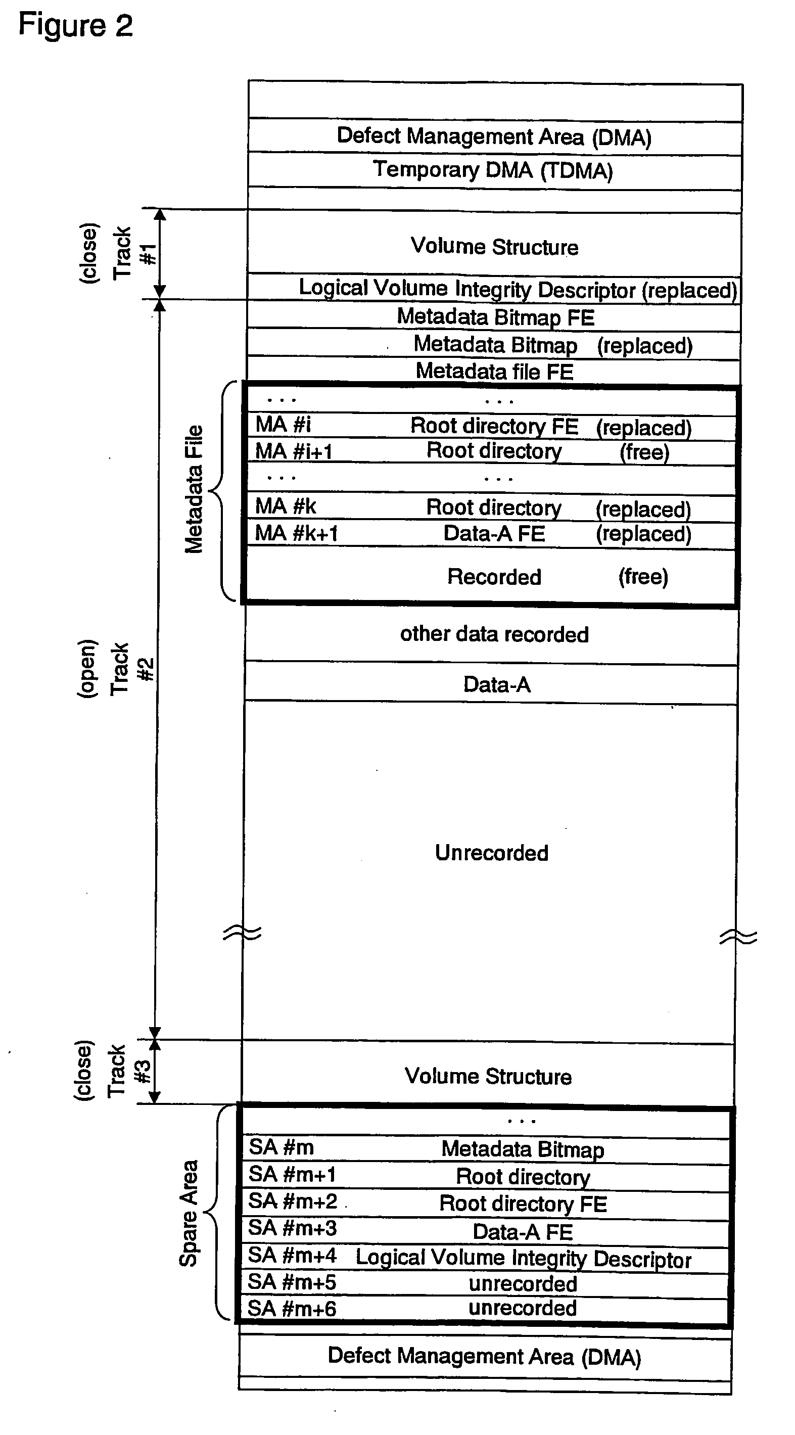
[0046]FIGS. 1 and 2 are diagrams showing a configuration of areas. FIG. 4 is a flowchart showing a procedure for recording a file. FIG. 1 shows the state where a file has been recorded after a logical format operation. FIG. 2 shows the state where a Data-A file has been recorded in a root directory on a disc having the state of FIG. 1.

[0047]Firstly, FIG. 1 will be described.

[0048]The data area includes the areas such as a Lead-in area, a volume space and a Lead-out area, (wherein the Lead-in area and the Lead-out area are managed by a physical layer). The physical sector is an addressable unit in ...

embodiment 2

[0077]This embodiment describes a further recording method to write a file onto a write-once disc on which the state is explained in embodiment 1 as FIG. 2.

[0078]In FIG. 2, the unrecorded area is only 2 sectors of SA #m+5 and #m+6, therefore, if the Metadata Bitmap and the root directory are written in the spare area, a file entry of the root directory, and a file entry of the file can not be written any more. Thus, an additional file can not be recorded, even if the Metadata Bitmap indicates available areas in the Metadata file, because the unrecorded area in the spare area is used up.

[0079]So, hereinafter a recording method to record the file with checking the size of unrecorded areas in the spare area is described.

[0080]FIG. 3 is a diagram illustrating a configuration of areas on the disc on which the same data as shown in FIG. 2 is written. In FIG. 3, as a spare area with the larger size has been provided by a logical formatting operation, the spare area has a larger unrecorded ...

embodiment 3

[0093]In the previous embodiment 2, the spare area with sufficient size has to be assigned at the time of formatting on a write-once disc. However, a user cannot know how many files and the size of the files that will be recorded on the disc, therefore, it is difficult to decide the appropriate size of the spare area at the time of formatting. If all of the spare area is used, no file can be recorded on the disc, even if the unrecorded area remains in the user data area. On the other hand, if a larger spare area is assigned, after all of the user data area is used, unrecorded area may remain in the spare area.

[0094]Further, a file system driver has to check the size of the unrecorded area in the spare area each time when a file is recorded, hence the space management becomes difficult to implement. This is not suitable for the implementation of file system driver of computer systems.

[0095]So, hereinafter a recording method in which the direction to replace the data not only within t...


PUM


Abstract

The recording method of the present invention includes the steps of: receiving a write instruction which specifies at least a logical sector in which data is to be written; determining whether the logical sector corresponds to a recorded physical sector or an unrecorded physical sector; when it is determined that the logical sector corresponds to an unrecorded physical sector, writing the data into the unrecorded physical sector, determining whether a verification of the data which has been written into a physical sector is successful, if the verification of the data that has been written is not successful, writing the data into an unrecorded physical sector, generating a remapping table including remapping information which remaps an original address of the physical sector corresponding to the logical sector to a remapping address of the selected physical sector, and writing the remapping table on the write-once disc.

Description

TECHNICAL FIELD[0001]The present invention relates to a recording method and apparatus for a write-once disc using a logical overwritable mechanism, a reproduction method and apparatus, and a semiconductor integrated circuit for use in the recording apparatus or the reproduction apparatus.BACKGROUND ART[0002]File systems for optical discs have made advances through various activities to develop UDF (Universal Disk Format®) specifications published from OSTA (Optical Storage Technology Association).[0003]For write-once discs, the recording method has improved from multi-session recording to file-by-file recording using VAT (Virtual Allocation Table).[0004]On the other hand, for rewritable discs, a volume and file structure has improved from the structure using non-sequential recording defined in ECMA 167, which is the international standard, to the structure using Metadata Partition specified in UDF Revision 2.5 (hereinafter UDF 2.5). The merits to use Metadata Partition are the impr...

Claims


Application Information

Patent Timeline
IPC IPC(8): G11B20/00G11B20/10G11B20/12G11B20/18G11B27/034G11B27/32
CPCG11B20/10G11B20/1879G11B20/1883G11B2020/10898G11B2020/10907G11B2220/2541G11B2020/1873G11B2020/1893G11B2220/20G11B2220/218G11B2020/1288G11B20/12G11B20/18G11B27/034G11B27/32
Inventor GHOTGE, VISHAL V.THIND, RAVINDER S.GOTOH, YOSHIHONAGAR, RAJEEV Y.BUBAN, GARRET J.HAVEWALA, SAROSH C.
Owner PANASONIC CORP
Why Eureka
Try Eureka