Touch screen using carbon nanotube electrodes

a carbon nanotube and electrode technology, applied in the field of touch screens having a resistance framing design, can solve the problems of touch screens malfunctioning and/or failing, screen malfunctioning and/or failing, and screen function differen

Inactive Publication Date: 2008-08-14
TE CONNECTIVITY CORP
View PDF10 Cites 166 Cited by
  • Summary
  • Abstract
  • Description
  • Claims
  • Application Information

AI Technical Summary

Problems solved by technology

However, environmental conditions to which touch screens may be subjected during storage and / or use may cause the electrical properties of conventional boundary electrodes to change from the original resistance at the time of manufacture.
A change in the electrical properties of the boundary electrode(s) may cause the touch screen to malfunction and / or fail, and at the least may cause the touch screen to function differently than intended.
Moreover, some environmental conditions to which touch screens may be subjected during manufacture, storage, and / or use may cause conventional boundary electrodes to fracture, fatigue, and / or separate from the electrically conductive coating.
Fracture, failure, and / or separation of the boundary electrode(s) may cause the electrical connection between the electrode(s) and the electrically conductive area to be interrupted.
Such interruption may cause the touch screen to malfunction, fail, and / or function differently than intended.
Inorganic materials of solid construction (e.g., tinned copper traces or sintered silver frit) may stand up generally well to environmental conditions, but are too conductive for use as boundary electrodes.

Method used


Image

  • Touch screen using carbon nanotube electrodes
  • Touch screen using carbon nanotube electrodes
  • Touch screen using carbon nanotube electrodes

Examples


Embodiment Construction

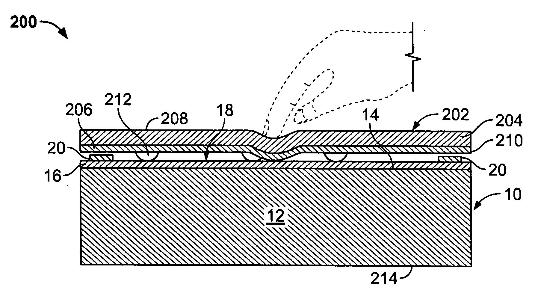
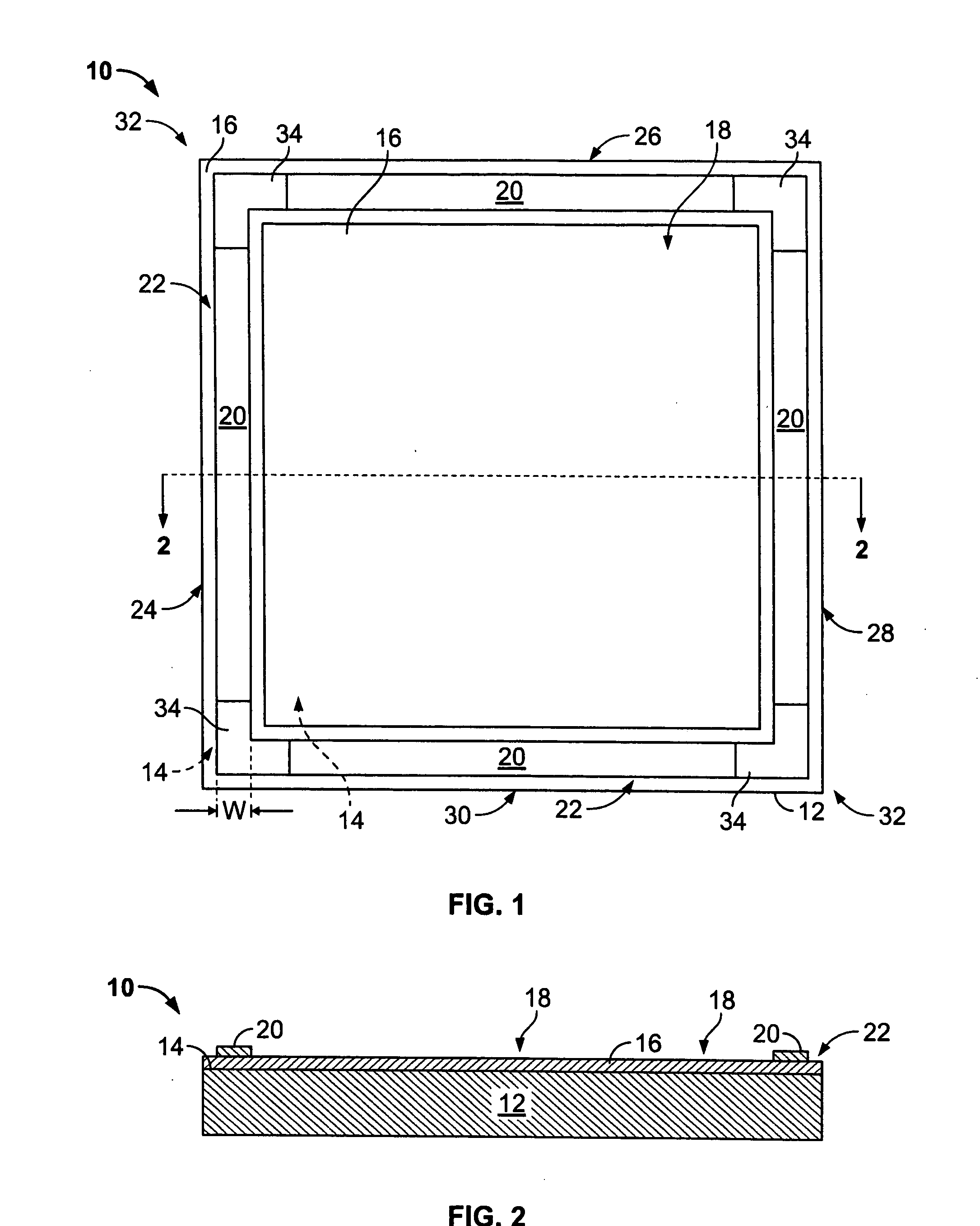
[0015]FIG. 1 is a top plan view of a touch screen substrate assembly 10 formed in accordance with an embodiment of the present invention. FIG. 2 is a cross-sectional view of the assembly 10 taken along line 2-2 of FIG. 1. The assembly 10 may be used with any suitable touch screen system, such as, resistive or capacitive systems. Exemplary touch screen systems incorporating the assembly 10 will be described in more detail below. The assembly 10 includes a substrate 12 having a surface 14 at least partially coated with an electrically conductive material 16. The electrically conductive material 16 coating the surface 14 provides an electrically conductive touch area 18 on the surface 14. One or more electrodes 20 frame at least a portion of the touch area 18. The electrodes 20 are formed at least partially from a structure including carbon nanotube, in which carbon nanotubes are the conducting elements.

[0016]The substrate 12 may be fabricated from any suitable material(s), that enable...


PUM

PropertyMeasurementUnit
thicknessaaaaaaaaaa
thicknessaaaaaaaaaa
widthaaaaaaaaaa

Abstract

A touch screen substrate assembly includes a substrate having a surface at least partially coated with an electrically conductive material to provide an electrically conductive touch area on the surface. At least one electrode is disposed over the substrate adjacent the touch area. The electrode is positioned over the substrate to extend continuously along at least a portion of a perimeter portion of the touch area. The electrode includes carbon nanotubes.

Description

BACKGROUND OF THE INVENTION[0001]The invention relates generally to computer touch screens, and more particularly, to touch screens having a resistance framing design.[0002]Since their introduction in the early 1970s, touch screens have afforded alternatives to keyboards for certain computer applications. In many situations the keyboard and mouse are eliminated, because the touch screen provides the user with access to the computer. Both resistive and capacitive touch screens typically include a substrate, such as a glass panel, that includes an electrically conductive coating, such as indium tin oxide (ITO), on a surface thereof. The electrically conductive coating defines an electrically conductive area on the substrate surface for accepting a user's inputs to the touch screen. An insulating layer is positioned over the electrically conductive area to provide a surface for the user to touch to select the inputs. For example, in a resistive touch screen, the insulating layer forms ...

Claims


Application Information

Patent Timeline
Patent Type & Authority Applications(United States)
IPC IPC(8): G06F3/041
CPCB82Y10/00H01L51/102H01L51/0048G06F3/041G06F3/045G06F3/044H10K85/221H10K10/82
Inventor KENT, JOEL C.SCHARFF, DANIEL H.
Owner TE CONNECTIVITY CORP
Why Eureka
Try Eureka