
Method and system for reducing backhaul utilization during base station handoff in wireless networks

a wireless communication system and wireless network technology, applied in the field of wireless communication, can solve the problems of large amount of data that needs to be transferred between base stations during a handoff event, difficulty in maintaining an older wireless network system, and system typically not as easily updated

Inactive Publication Date: 2008-08-07
QUALCOMM INC
View PDF7 Cites 99 Cited by
  • Summary
  • Abstract
  • Description
  • Claims
  • Application Information

AI Technical Summary

Benefits of technology

[0009]The following presents a simplified summary in order to provide a basic understanding of some aspects of the disclosed embodiments. This summary is not an extensive overview and is intended to neither identify key or critical elements nor delineate the scope of such embodiments. Its purpose is to present some concepts of the described embodiments in a simplified form as a prelude to the more detailed description that is presented later.

Problems solved by technology

Such systems typically are not as easily updated as the cellular devices that communicate there over.
As mobile device capabilities expand, it can be difficult to maintain an older wireless network system in a manner that facilitates fully exploiting new and improved wireless device capabilities.
Independently of the technique employed to accomplish a wireless communication, in certain wireless networks the amount of data that needs to be transferred between base stations during a handoff event may be large due to a large amount of data buffered at a base station when handoff is necessary.
One important cause is the absence of tight flow control between the access gateway and the base station.
Such a substantial data transfer can significantly increase bandwidth requirement at a base station.
Proprietary solutions are expensive and hardly transferable.

Method used


Image

  • Method and system for reducing backhaul utilization during base station handoff in wireless networks
  • Method and system for reducing backhaul utilization during base station handoff in wireless networks
  • Method and system for reducing backhaul utilization during base station handoff in wireless networks

Examples


Embodiment Construction

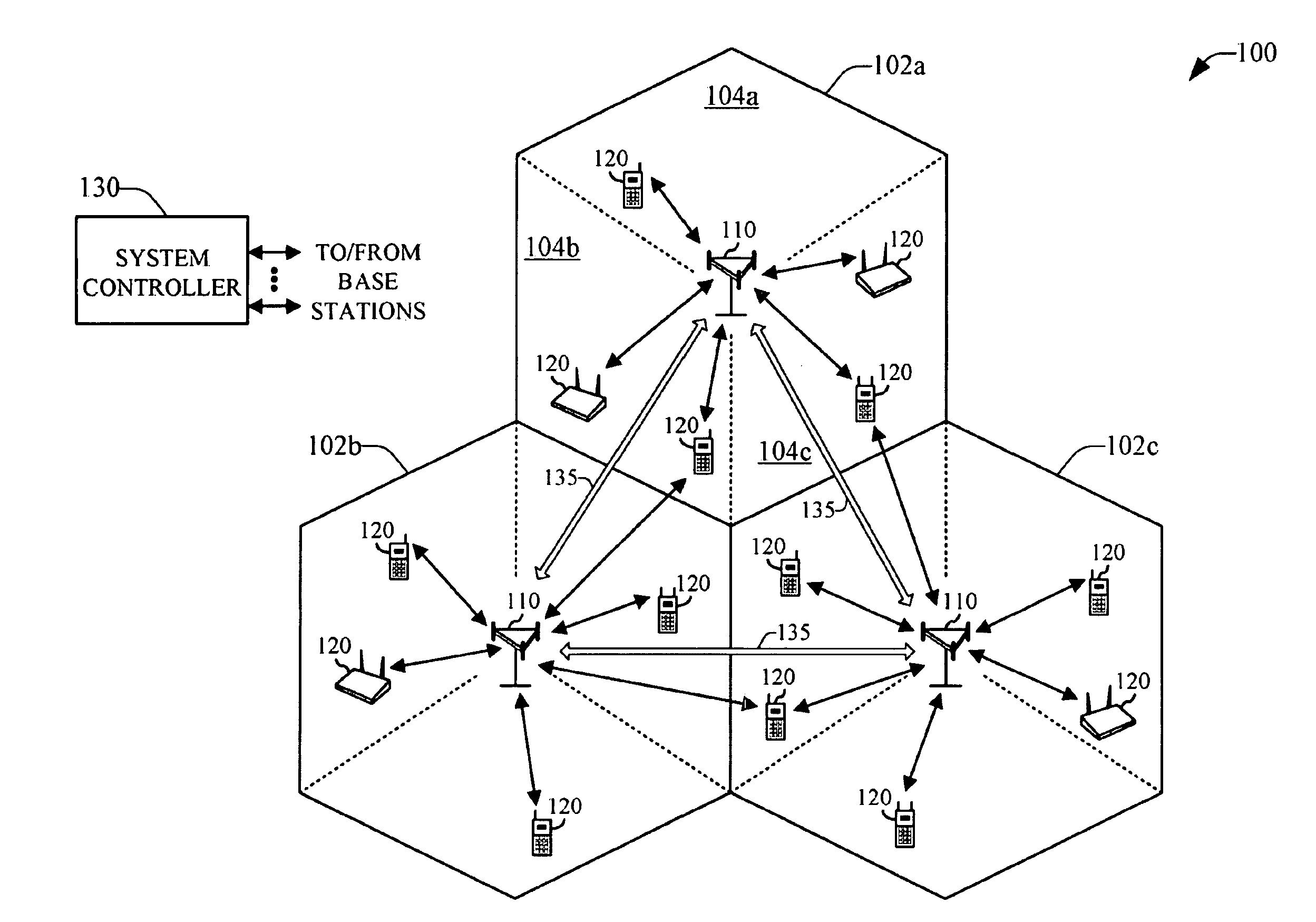
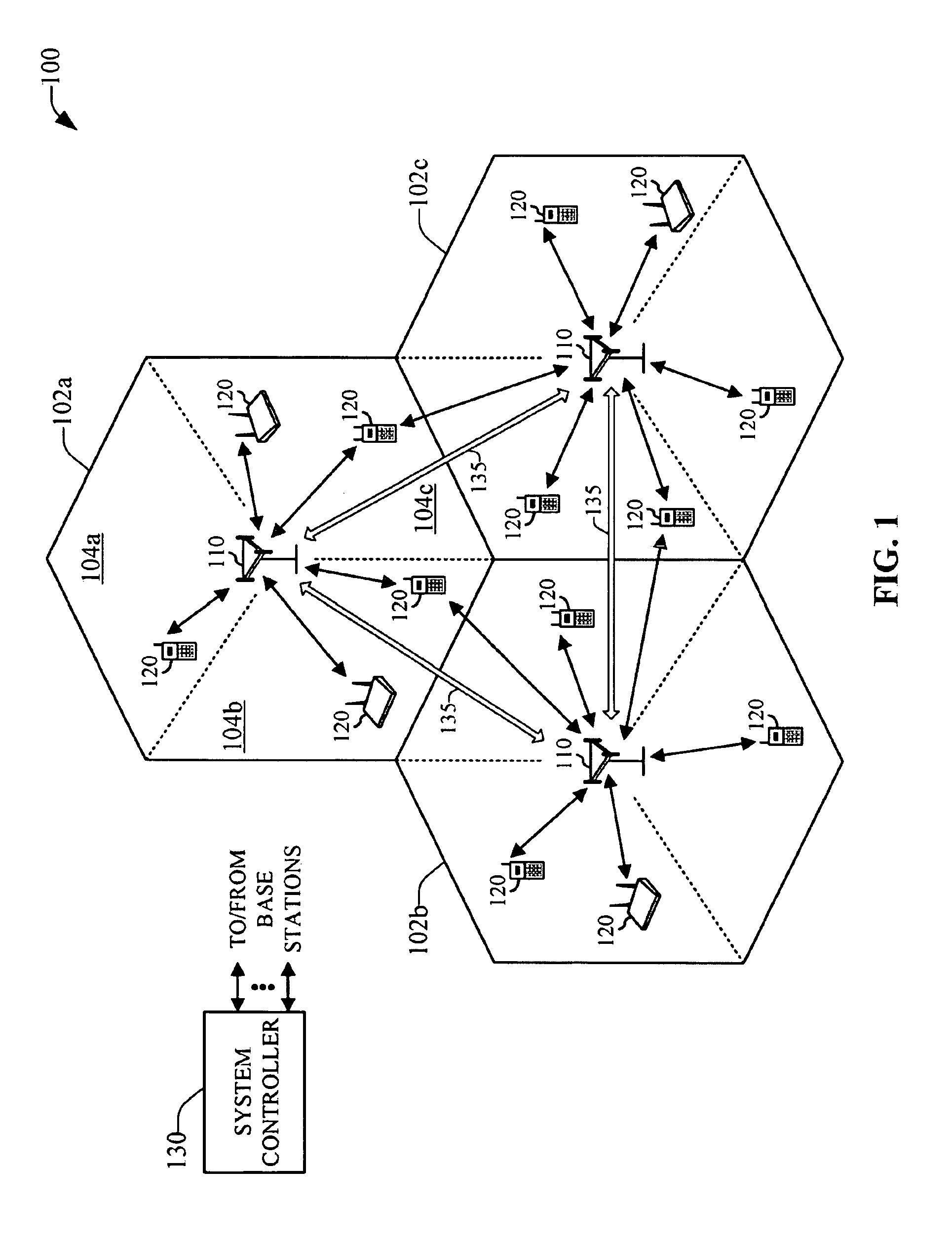
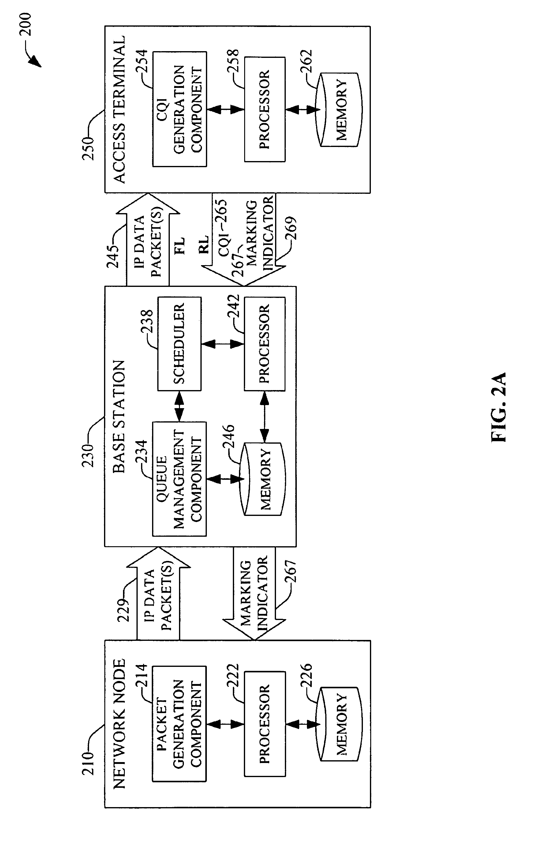
[0031]Various embodiments are now described with reference to the drawings, wherein like reference numerals are used to refer to like elements throughout. In the following description, for purposes of explanation, numerous specific details are set forth in order to provide a thorough understanding of one or more embodiments. It may be evident, however, that such embodiment(s) may be practiced without these specific details. In other instances, well-known structures and devices are shown in block diagram form in order to facilitate describing one or more embodiments.

[0032]As used in this application, the terms “system,”“component,”“module,”“application,” and the like are intended to refer to a computer-related entity, either hardware, firmware, a combination of hardware and software, software, or software in execution. For example, a component may be, but is not limited to being, a process running on a processor, a processor, an object, an executable, a thread of execution, a program...


PUM


Abstract

Systems and methods are provided that facilitate active queue management of internet-protocol data packets generated in a data packet switched wireless network. Queue management can be effected in a serving base station as well as in an access terminal, and the application that generates the data packets can be executed locally or remotely to either the base station or access terminal. Management of the generated data packets is effected via a marking / dropping of data packets according to an adaptive response function that can be deterministic or stochastic, and can depend of multiple communication generalized indicators, which include packet queue size, queue delay, channel conditions, frequency reuse, operation bandwidth, and bandwidth-delay product. Historical data related to the communication generalized indicators can be employed to determine response functions via thresholds and rates for marking / dropping data packets.

Description

CLAIM OF PRIORITY UNDER 35 U.S.C. §119[0001]This application for patent claims the benefit of U.S. Provisional Application Ser. No. 60 / 868,711 filed on Dec. 5, 2006, and entitled “METHOD AND SYSTEM FOR REDUCING BACKHAUL UTILIZATION DIRING BASE STATION HANDOFF IN WIRELESS NETWORKS.” The entirety of this application is expressly incorporated herein by reference.BACKGROUND[0002]1. Field[0003]The subject disclosure relates generally to wireless communication and more particularly to base station handoff in wireless communication systems.[0004]2. Background[0005]Wireless communication systems have become a prevalent means by which a majority of people worldwide have come to communicate. Wireless communication devices have become smaller and more powerful in order to meet consumer needs and to improve portability and convenience. The increase in processing power in mobile devices such as cellular telephones has lead to an increase in demands on wireless network transmission systems. Such ...

Claims


Application Information

Patent Timeline
Patent Type & Authority Applications(United States)
IPC IPC(8): H04Q7/00H04W72/12H04W72/14H04W80/04
CPCH04L47/10H04L47/14H04L47/263H04L47/30H04L47/31Y02B60/31H04L47/326H04W28/22H04W72/1205H04W80/04H04L47/32H04W28/0284H04W72/12H04L47/2458Y02D30/50H04W8/04
Inventor TINNAKORNSRISUPHAP, PEERAPOLWANG, JUNAGASHE, PARAG ARUN
Owner QUALCOMM INC
Learn More