Method of measuring gap depth of thin film magnetic head for horizontal magnetic recording, and method of measuring neck height of thin film magnetic head for vertical magnetic recording

Inactive Publication Date: 2008-08-07
FUJITSU LTD
View PDF0 Cites 3 Cited by
  • Summary
  • Abstract
  • Description
  • Claims
  • Application Information

AI Technical Summary

Benefits of technology

[0023]An object of the present invention is to provide a method of measuring a gap depth of a thin film magnetic head for horizontal magnetic recording, in which a position of a floating surface is defined on the basis of a width of a lapping guide in an anteroposterior direction (a direction perpendicular to the floating surface) and the gap depth of a write-magnetic pole can be easily and correctly measured without being influenced by shrink, etc. in a step of etching the lapping guide.
[0072]In the method of the present invention for measuring the gap depth of the thin film magnetic head for horizontal magnetic recording, the gap depth of the write-magnetic pole can be easily and correctly measured without being influenced by shrink, etc. in the step of etching the lapping guide. On the other hand, in the method of the present invention for measuring the neck height of the thin film magnetic head for vertical magnetic recording, the neck height of the write-magnetic pole can be easily and correctly measured without being influenced by shrink, etc. in the step of etching the lapping guide.

Problems solved by technology

Therefore, it is impossible to perform the breaking test with a lot of samples.

Method used


Image

  • Method of measuring gap depth of thin film magnetic head for horizontal magnetic recording, and method of measuring neck height of thin film magnetic head for vertical magnetic recording
  • Method of measuring gap depth of thin film magnetic head for horizontal magnetic recording, and method of measuring neck height of thin film magnetic head for vertical magnetic recording
  • Method of measuring gap depth of thin film magnetic head for horizontal magnetic recording, and method of measuring neck height of thin film magnetic head for vertical magnetic recording

Examples


first embodiment

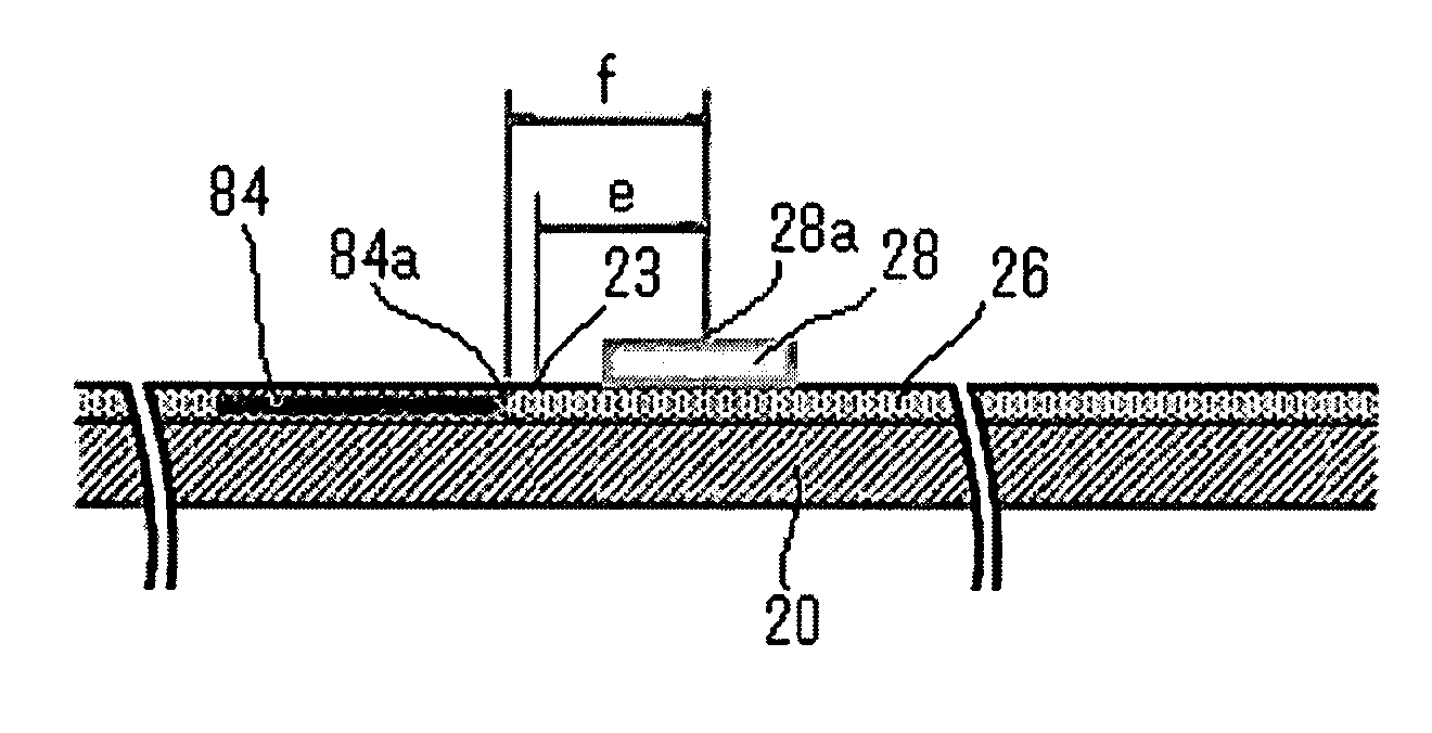
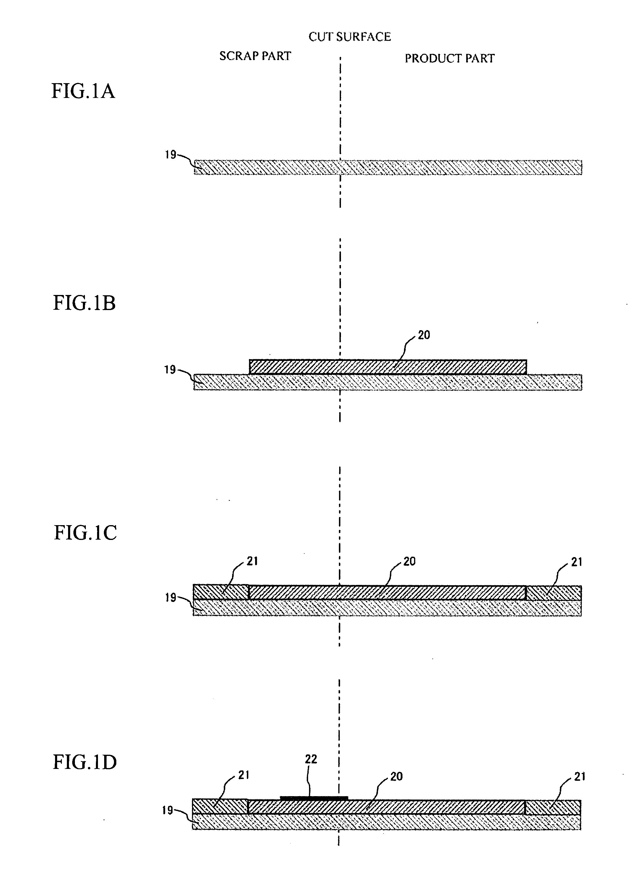
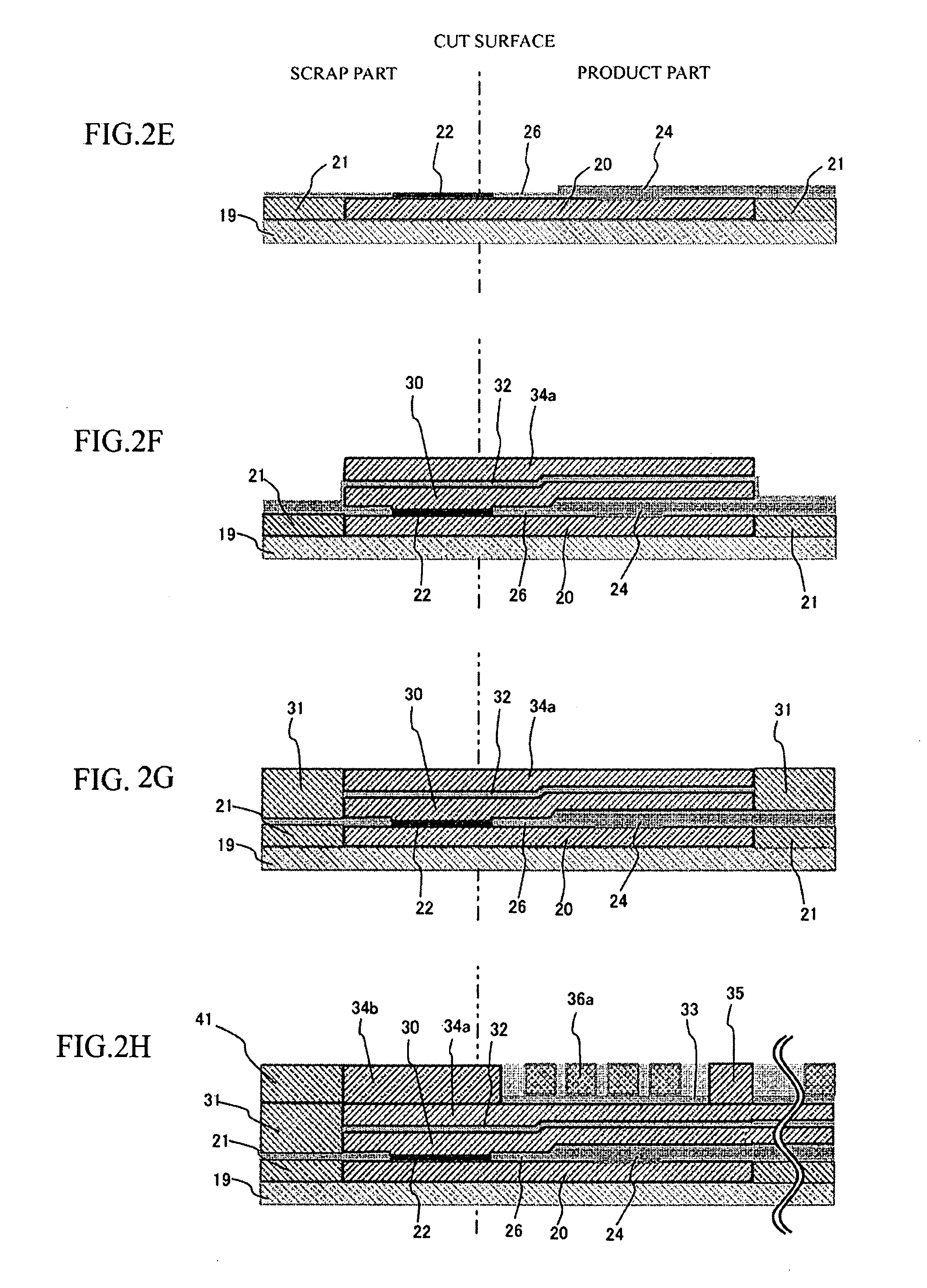
[0091]Firstly, a process for producing a thin film magnetic head for horizontal magnetic recording shown in FIG. 7 will be explained with reference to FIGS. 1A-3K, which are side sectional views. Note that, in FIGS. 1A-3K, a “cut surface” along a two-dot chain line indicates a floating surface of the completed thin film magnetic head. A “product part” will be left as the completed thin film magnetic head; a “scrap part” will be removed, from the completed thin film magnetic head, in a lapping step for forming the floating surface.

[0092]In FIG. 1A, a wafer substrate 19 is constituted by an AlTiC base and an insulating film, which is composed of alumina and formed on the AlTiC base by sputtering.

[0093]In FIG. 1B, a lower shielding layer 20 of a read-head is formed by wet plating. For example, the lower shielding layer 20 is formed by the steps of: forming a power feed layer for plating on the entire surface of the wafer substrate 19 by sputtering; forming a photoresist layer, which ha...

second embodiment

[0155]A method of measuring a neck height of a thin film magnetic head for vertical magnetic recording will be explained.

[0156]FIG. 9 is an anteroposterior sectional view of the thin film magnetic head for vertical magnetic recording. FIG. 10 is an explanation view of a write-main magnetic pole 80 of the thin film magnetic head seen from the upper side.

[0157]As shown in FIG. 10, the write-main magnetic pole 80 of the thin film magnetic head for vertical magnetic recording has: a neck section 80a, which is a front end part located on the floating surface 48 side and whose core width is constant and narrow; and a yoke section 80b, which is a rear end part and whose width is gradually increased toward the rear end from the neck section 80a. In the present invention, a border between the neck section 80a and the yoke section 80b is called a neck leader 80c. The neck height j is a distance between the neck leader 80c and the floating surface 48, i.e., a length of the neck section 80a aft...


PUM


Abstract

By the method of measuring a gap depth of a thin film magnetic head for horizontal magnetic recording, the gap depth of a write-magnetic pole can be easily and correctly measured. The method comprises the steps of: forming a first standard marker; measuring a distance between an actual position of a rear end of a lapping guide and the position of the first standard marker; calculating a lapping guide shift length; forming a second standard marker; measuring a distance between an actual position of a zero throat and a position of the second standard marker; calculating a zero throat shift length; and calculating an actual gap depth of a write-magnetic pole by adding the lapping guide shift length and the zero throat shift length to a designed gap depth.

Description

BACKGROUND OF THE INVENTION[0001]The present invention relates to: a method of measuring a gap depth of a thin film magnetic head for horizontal magnetic recording, wherein the gap depth is a distance between a front end of a write-magnetic pole exposed in a floating surface and a zero throat thereof and wherein a position of the floating surface is defined on the basis of a width of a lapping guide in an anteroposterior direction perpendicular to the floating surface in a step of forming the floating surface by a lapping process; and a method of measuring a neck height of a thin film magnetic head for vertical magnetic recording, wherein the neck height is a distance between a front end of a write-main magnetic pole exposed in a floating surface and a neck leader thereof and wherein a position of the floating surface is defined on the basis of a width of a lapping guide in an anteroposterior direction perpendicular to the floating surface in a step of forming the floating surface b...

Claims


Application Information

Patent Timeline
IPC IPC(8): G01B11/22
CPCG11B5/3169G11B5/3189G11B5/3173
Inventor ONO, RYUEI
Owner FUJITSU LTD
Why Eureka
Try Eureka