Optically driven carbon nanotube actuators
a technology of carbon nanotubes and actuators, which is applied in the field of optically driven carbon nanotube actuators, can solve the problems of difficult direct conversion of optical photon energy to mechanical energy, and achieve the effect of high feature resolution, fast etching of carbon nanotubes 14, and high resolution
- Summary
- Abstract
- Description
- Claims
- Application Information
AI Technical Summary
Benefits of technology
Problems solved by technology
Method used
Image
Examples
example 1
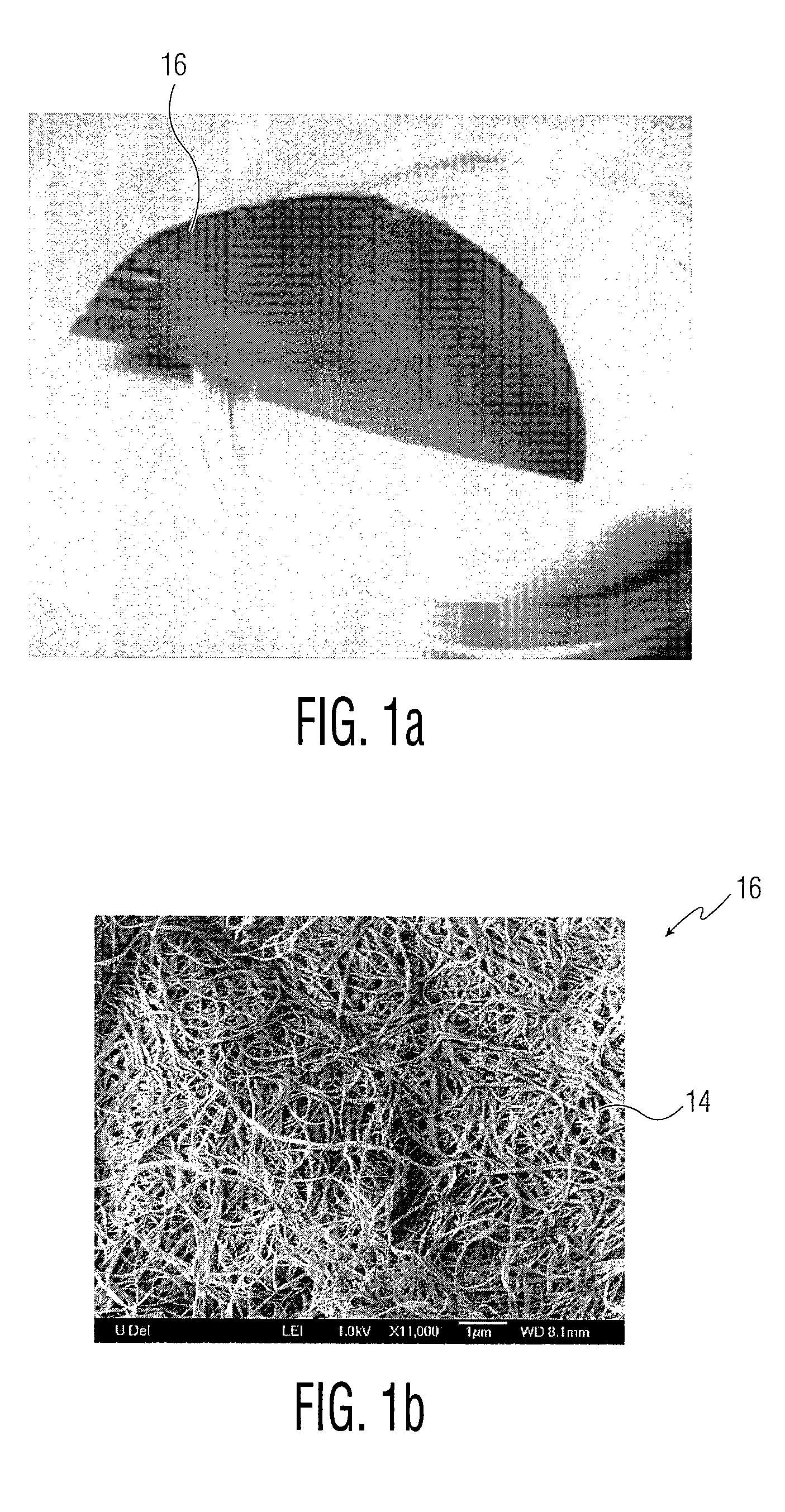
[0047]Referring to FIGS. 1(a) and 1(b), SWNT sheets 16 were fabricated using methane based chemical vapor deposition. In particular, FIG. 1(a) is an image illustrating an example of a SWNT sheet 16 formed by vacuum filtration and FIG. 1(b) is a scanning electron microscopy (SEM) image of SWNT sheet 16 composed of highly entangled SWNT bundles 14 (i.e. nanotubes). The diameter of the illustrated nanotubes 14 range from 1.3 nm to 1.4 nm, measured using transmission electron microscopy (TEM) images of nanotubes 14. SWNTs 14 (80 mg) were dispersed in 100 ml of iso-propyl alcohol and agitated for 20 hours to disperse the nanotubes uniformly in solution, providing a final SWNT concentration of 0.8 mg / ml. The SWNT (20 ml) suspension was filtrated through a poly(tetrafluoroethylene) filter (47 mm in diameter) by vacuum filtration. The resulting SWNT sheet 16 on the filter was rinsed twice with iso-propyl alcohol and deionized water and then dried at 80° C. for 1 hour to further remove the r...
example 2
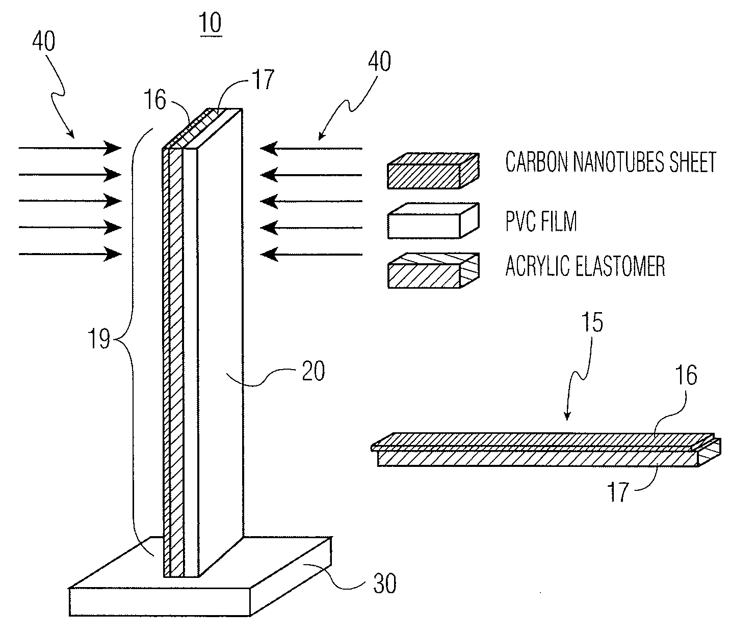
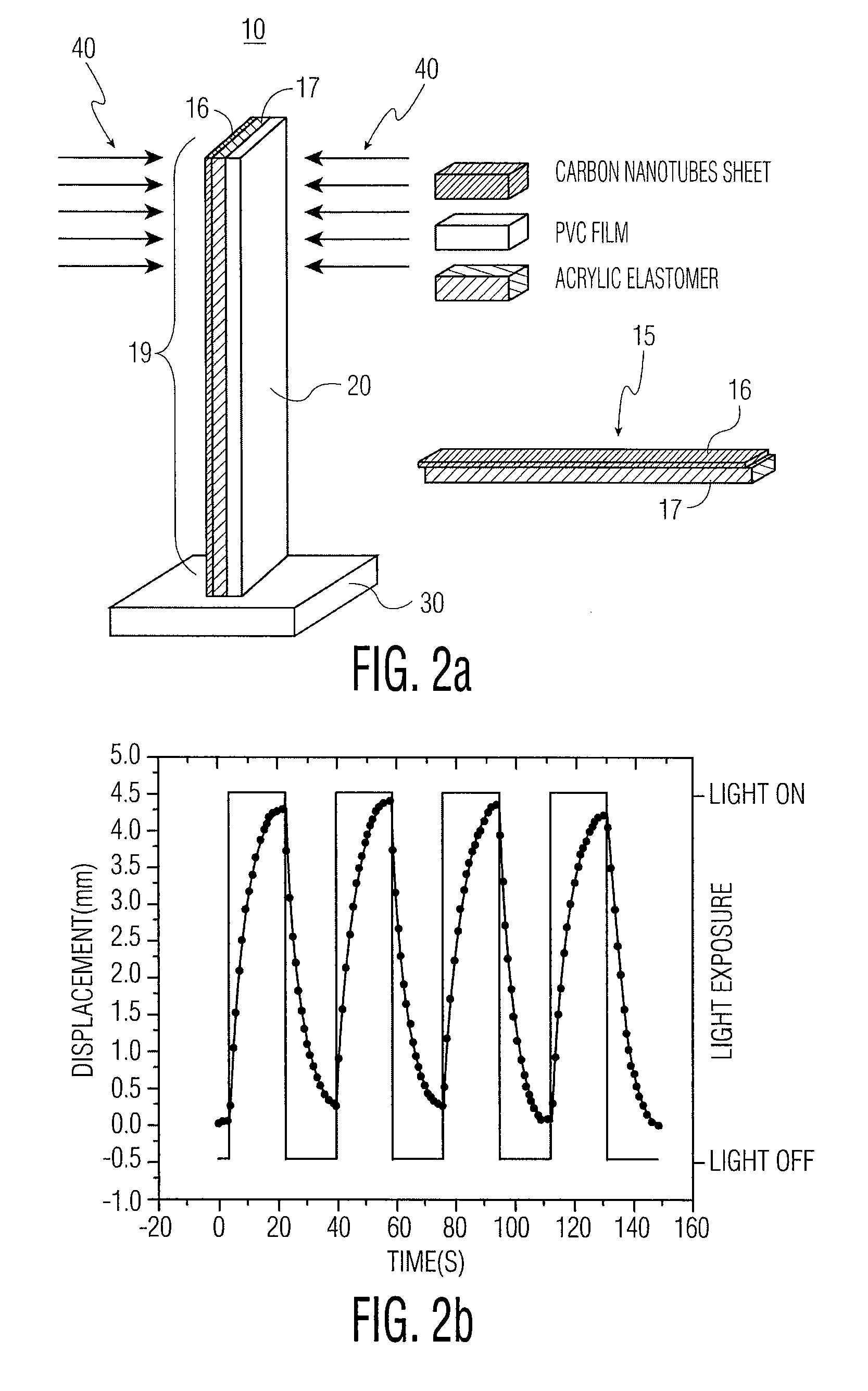
[0049]Referring to FIGS. 2(a) and 2(b), an exemplary cantilever structure 10 was formed according to an exemplary embodiment. In particular, FIG. 2(a) illustrates a cantilever system including bimorph actuator 15 and PVC film 20 of 100 μm in thickness together forming exemplary cantilever beam 19, where cantilever beam 19 is vertically anchored on base 30 to form cantilever structure 10; and FIG. 2(b) is a graph depicting an actuation response of cantilever structure 10 with respect to time when light is switched between “on” and “off” settings.
[0050]Cantilever beam 19 was formed by attaching bimorph actuator 15 (described with respect to Example 1) to PVC film 20 having the same dimensions as bimorph actuator 15 but with a thickness of 100 μm. FIG. 2(a) shows cantilever beam 19 anchored on base 30, which may bend in a direction normal to the cantilever surface. Bimorph actuator 15 is shown in the lower right of this figure formed of acrylic elastomer 17 and SWNT sheet 16. A halogen...
example 3
[0052]Referring to FIGS. 3(a), 3(b) and 3(c), in order to characterize the strain of the actuator under light exposure, another exemplary actuation system was designed. In particular, FIG. 3(a) illustrates an experiment for strain characterization, where exemplary bimorph actuator 15′ is attached between vertical anchor 50 and PVC film 20′ of 100 μm in thickness, a stress from bimorph actuator 15′ bends PVC film 20′, and a displacement of a top of PVC film 20′ is recorded by digital camera system 60; FIG. 3(b) is a graph illustrating the strain of exemplary actuator 15′ under different white light intensity ranging from 70 mW / cm2 (black), 40 mW / cm2 (red), and 20 mW / cm2 (green); and FIG. 3(c) is a graph illustrating the strain response as a function of white light intensity.
[0053]As shown in FIG. 3(a), bimorph actuator 15′ was double clamped between vertical anchor 50 and PVC film 20. PVC film 20 was 100 μm in thickness and was also fixed vertically on base 30. Actuator 15′ is the sa...
PUM
 Abstract
Description
Claims
Application Information
 - R&D
- Intellectual Property
- Life Sciences
- Materials
- Tech Scout
- Unparalleled Data Quality
- Higher Quality Content
- 60% Fewer Hallucinations
Browse by: Latest US Patents, China's latest patents, Technical Efficacy Thesaurus, Application Domain, Technology Topic, Popular Technical Reports.
© 2025 PatSnap. All rights reserved.Legal|Privacy policy|Modern Slavery Act Transparency Statement|Sitemap|About US| Contact US: help@patsnap.com


