
Variable pixel binning in an optical biometric imaging device

A technology of biometrics and imaging devices, which is applied in the recognition of patterns in signals, image communication, and printing image acquisition, etc., can solve the problems of reduced biometric performance and reduced image resolution, etc.

Pending Publication Date: 2021-08-13
FINGERPRINT CARDS ANACATUM IP AB
View PDF0 Cites 0 Cited by
  • Summary
  • Abstract
  • Description
  • Claims
  • Application Information

AI Technical Summary

Problems solved by technology

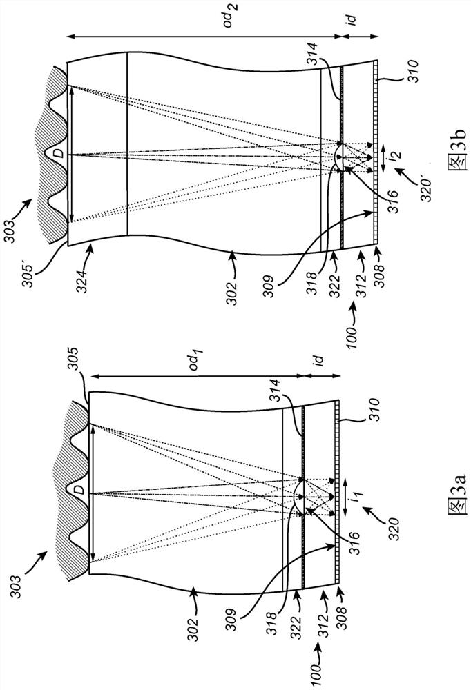
[0005] For example, if the object distance increases, the image resolution will decrease and this will result in lower biometric performance

Method used


Image

  • Variable pixel binning in an optical biometric imaging device
  • Variable pixel binning in an optical biometric imaging device
  • Variable pixel binning in an optical biometric imaging device

Examples


Embodiment Construction

[0062] In this detailed description, various embodiments of a biometric imaging device according to the present invention are described mainly with reference to a biometric imaging device arranged under a display panel. It should be noted, however, that the described biometric imaging device may also be used in other biometric imaging applications, such as in biometric imaging devices located under a cover glass or the like.

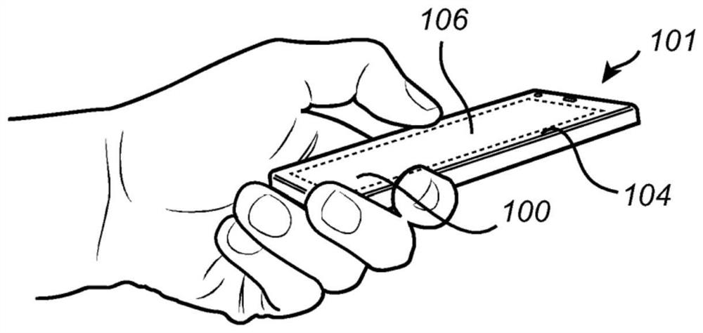
[0063] Turning now to the drawings, and in particular to figure 1 , figure 1 An example of an electronic device configured to apply concepts according to the present disclosure is schematically shown in the form of a mobile device 101 having an integrated in-display optical biometric imaging device 100 and a display panel 104 with a touch screen interface 106 . The optical biometric imaging device 100 may be used, for example, to unlock the mobile device 100 and / or to authorize transactions performed using the mobile device 100, among other things.

...


PUM


Abstract

The present invention relates to a method of configuring an optical biometric imaging device comprising a photo-detector pixel array, the method comprising: acquiring a biometric image of a biometric object using a first binning setting for binning of detection signals from sub-arrays of the photo-detector pixels into a single pixel value;determining a measure indicative of the feature resolution of the biometric image; and determining, when the measure indicates that the feature resolution is below a feature resolution threshold, a second binning setting adapted to provide a higher feature resolution compared to the feature resolution of the biometric image.

Description

technical field [0001] The present invention relates to a method of configuring an optical biometric imaging device comprising an array of photodetector pixels, an optical biometric imaging device and a computer program product. Background technique [0002] Biometric systems are widely used as a means for increasing the convenience and security of personal electronic devices such as mobile phones. In particular, fingerprint sensing systems are now included in the majority of all newly released consumer electronic devices such as mobile phones. [0003] Optical fingerprint sensors have been known for some time and may be a viable alternative to, for example, capacitive fingerprint sensors in certain applications. Optical fingerprint sensors may, for example, be based on the principle of pinhole imaging and / or may employ micro-channels (ie collimators or micro-lenses) to focus incident light onto the image sensor. [0004] In an optical fingerprint sensor, the image under t...

Claims


Application Information

Patent Timeline
Patent Type & Authority Applications(China)
IPC IPC(8): G06K9/00H04N5/347G06V10/10G06V10/147G06V40/13H04N25/42H04N25/46
CPCG06V40/1329G06V40/1318G06V10/147G06V10/17H04N25/42H04N25/46G06F21/32G06F2218/02
Inventor 汉斯·马丁松
Owner FINGERPRINT CARDS ANACATUM IP AB
Learn More