
Infant food & debris catcher

a technology for catching debris and food, which is applied in the field of infant food & debris catcher, can solve the problems of large waste of a large sheet, food, utensils and food containers spillage, sticky mess on the floor, etc., and achieve the effect of little ability and minimal disruption or distraction

Inactive Publication Date: 2008-08-07
ROMANIUK JOHANNA LOUISE
View PDF11 Cites 7 Cited by
  • Summary
  • Abstract
  • Description
  • Claims
  • Application Information

AI Technical Summary

Benefits of technology

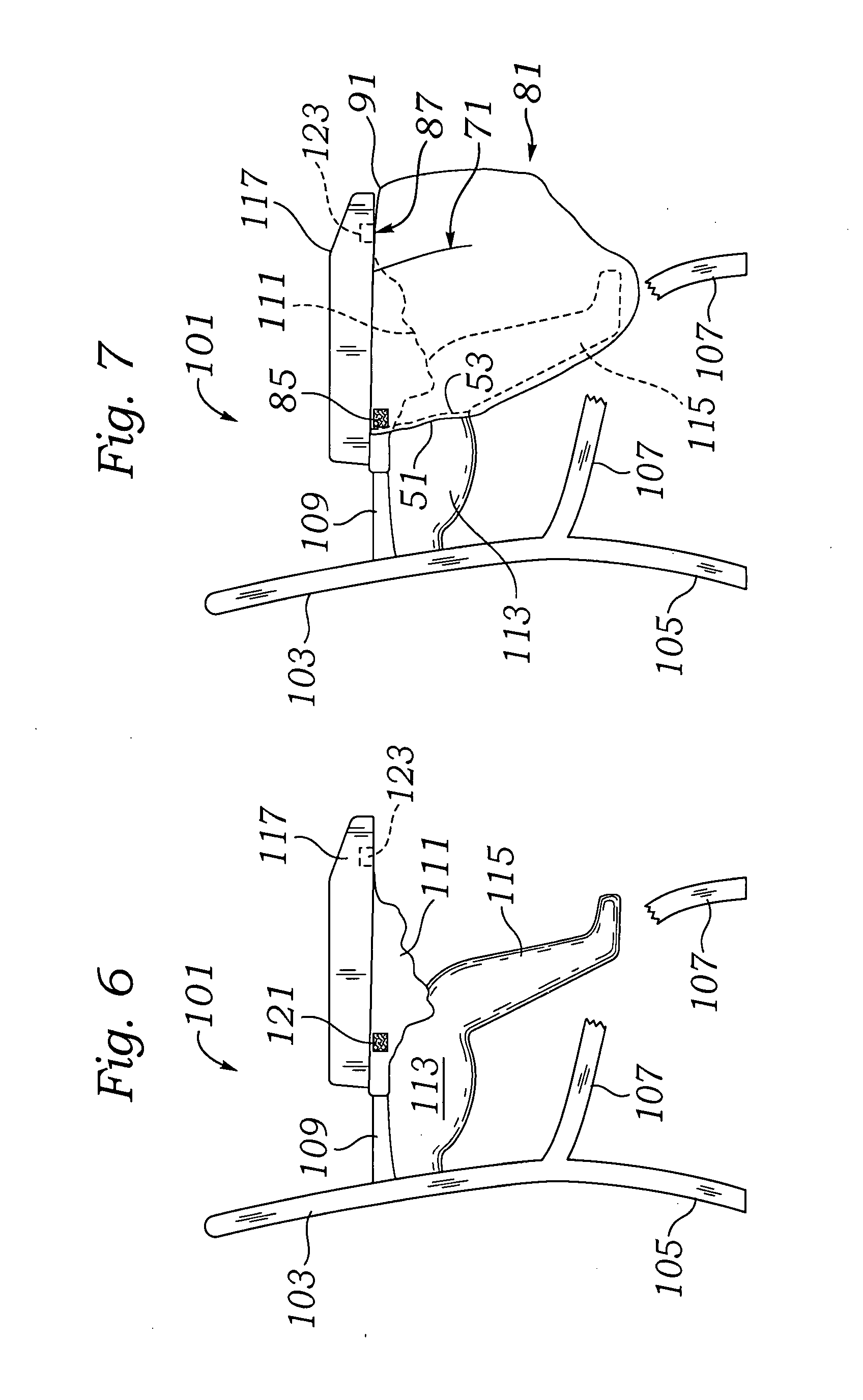
[0009]The catcher may preferably have attachment points to the underside of the high chair tray, or other forward member, as well as to the high chair tray support, including horizontal and vertical parts of the high chair arms. The catcher has a lower structure which may be preferably engaged about a lower structure on the high chair such as a foot rest or other convenient structure the high chair may have. Such lower engagement may be accomplished through a contractible urged edge or some other engagement structure which may or may not be elastically urged. The catcher may have internal structures which range from additional areas of material to seams to stiffening members where it is desired to promote a given shape.
[0011]The catcher is compact and easily rinsed by hand and can be made of such thin material that it is unnecessary to take special procedures to dry it. In most instances it is not necessary to have to wait for it to dry before reattaching it to the highchair.
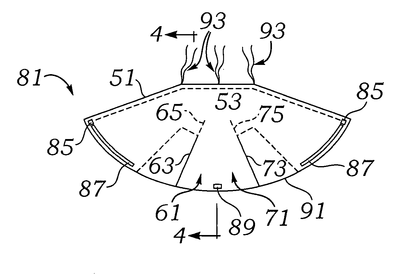
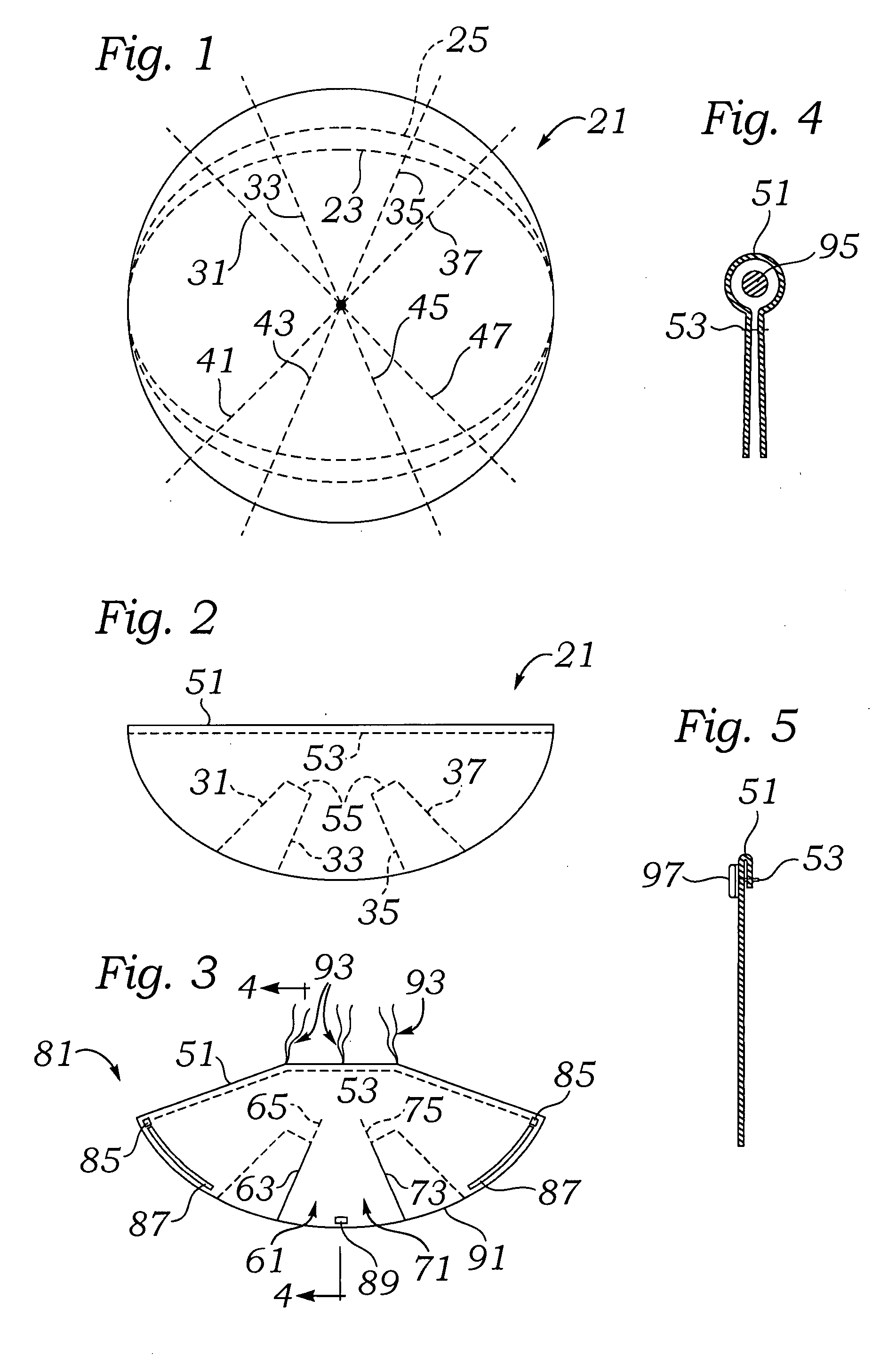
[0013]The catcher may be of a “rip stop nylon” material. It may be water impervious and as lightweight as possible. Such material will enable the catcher constructed to not only be lightweight, but also washable and to dry quickly. The catcher, when stretched flat approximates a half moon in shape. The construction of one embodiment of the catcher may preferably start with a circle of material, and then folded to a two ply semi circle. Elastic may be attached to operate within or adjacent the fold to cause it to contract. Attachment members may be attached at one or more points adjacent the curved periphery for attachment to corresponding attachment areas on the high chair, such as under the tray, adjacent the arms or arm supports. “Darts” or wedge shaped cutouts may occur along the periphery in order to shorten its radial extent, eliminate the need or tendency to form pleats or open gaps in the upper portion when placed against the tray, or generally to assist in forming a convex front profile. The darts may be adjusted in angular width and depth to achieve the convex shape (viewed from the front of the high chair and side profile of the high chair. In terms of the filled-out concave shape of the catcher as it is attached to a high chair, the darts not only eliminate folds which might be formed upon a snug fit to the high chair tray, but also generally help to form the side edges of the concave shape and define the transition from the front of the catcher to its sides. In essence, the darts eliminate the need for thick pleats at the front top of the catcher and enable the front top to be so lightweight as to be almost self supporting, although additional attachment members may be present. The shape of the darts can be modified to give shape effects to the convex front of the catcher once it is in place.
[0015]Ideally, the catcher may have a minimum of one and preferably two or more pairs of generally symmetrically oppositely located attachment members. In this configuration, the more forward pair of attachment member attach to the high chair food tray at forward most points adjacent the “turn” of the edges of the catcher toward each other to form the front panel. A rearward most pair of attachment members provide rearward most attachment locations holding up the catcher adjacent and high with respect to the location of the legs of the child. These rearward most attachment points help hold a continuation of the rearward extent of the upper part of the catcher, and also provide force and support against the lowermost portion of the catcher which may be elastically urged against the underside of the foot support, if present.
[0016]It is preferred that the high chair have at least a partially downwardly and partially forwardly disposed portion of the front seat which may be a foot support or may be a leg guide. In modern high chairs, the seat may be molded to comfortably conform to the child's body and provide a leg guide integral with the seat to gently guide most of the child's body and shield it from any sharp edges or other undesirable surfaces. As a result, most modern high chairs have a leg guide possibly terminating in a forward extending foot support. The ability of the catcher to engage some rearward portion of the leg guide enables the catcher to be used with very little interaction with the child. In essence, the child will only be able to make contact with the catcher by stretching his or her legs to the side near the support points, with the catcher providing a significantly spaced forward enveloping area which many children may not be able to contact.
[0017]In the configuration described, the catcher is able to be used with minimum disruption or distraction of the child and very little ability of the child to remove the catcher. Further, the catcher is such that it has a broad front area to support patterns, colors, and promotional logos and names.

Problems solved by technology

Regardless of the extent to which training has occurred, nearly any interaction by the child will result in food, utensil and food container spillage.
Consequently, there is a sticky, mushy mess on the floor that must be cleaned.
Further, the trays protruding from the sides of the high chair are easy for adults to trip over and run into resulting in injury.
Disposability results in significant waste for a large sheet, whereas cleaning the sheet may be as difficult as cleaning food from the floor.
This device cannot easily move with the high chair to another location.

Method used


Image

  • Infant food & debris catcher
  • Infant food & debris catcher
  • Infant food & debris catcher

Examples


Embodiment Construction

[0027]The description, construction and operation of the catcher of the invention will be best illustrated by beginning with the construction of the catcher. An expanse of material 21 is provided which may be cut to a circular shape or to an oval shape. Material 21 may preferably be made from polyurethane having a thickness of perhaps 3 mils. An alternative set of cutting lines are seen as cutting line 23 which may preferably form a blended radius for reduction of the effective radius by about 75% and a cutting line 25 which may preferably form a blended radius for reduction of the effective radius by about 83%.

[0028]A pair of dart cutting lines 31 and 33 and a pair of dart cutting lines 35 and 37 are shown on the upper half of the expanse of material 21. A pair of dart cutting lines 41 and 43 and a pair of dart cutting lines 45 and 47 are shown on the lower half of the expanse of material 21.

[0029]The expanse of material can be any size, but may have a maximum radius of about sixty...


PUM


Abstract

An easily attachable, washable food, utensil and debris catcher device is easily fitted to all types of commercially available high chairs using a wide variety of attachment structures and operates to hold any small items or food spilled in the area of the child's seat and legs which would otherwise pass through to the floor. The catcher is designed to be attached to and detached from the high chair quickly and easily, yet can be attached for long periods of time especially where it is employed to catch dry objects such as toys or dry food such as whole peas or cereal. The catcher can be made from a wide range of material and can employ a wide range of attachment systems, including snap members, hook and loop members, hook and eyelet members, and latch members to name a few. Construction of the catcher is illustrated as well as variations in the construction which may enable the shape of the deployed catcher to be altered as well as one and two ply versions.

Description

FIELD OF THE INVENTION[0001]The present invention relates to a safe, convenient, easy to attach and remove structure and method for capture and disposal of food and debris dropped by an infant from a seating structure resulting in reduced cleanup for child care givers.BACKGROUND OF THE INVENTION[0002]Children are typically seated in high chairs during mealtime for a variety of reasons. Advantages include mealtime socialization, the ability to interact with the child at seated level, the ability to reach and help the child at mealtime, and the ability to keep the child orderly. One of the main purposes of the use of a high chair is to transition from having the parent feed the child to having the child feed himself / herself. Children are either fed or allowed to feed themselves using a plate of food placed on a table tray or other forward member attached to nearly all high chairs.[0003]Regardless of the extent to which training has occurred, nearly any interaction by the child will re...

Claims


Application Information

Patent Timeline
IPC IPC(8): A47D15/00
CPCA47D1/008A47D15/00
Inventor ROMANIUK, JOHANNA LOUISE
Owner ROMANIUK JOHANNA LOUISE
Learn More