Fuel pump module and method of producing the same

a technology of fuel pump and fuel pump module, which is applied in the direction of machines/engines, metal-working apparatus, and feed systems, can solve the problems of difficulty for operators to watch fuel, and achieve the effect of easy connection and accurate connection

Inactive Publication Date: 2008-08-07
DENSO CORP
View PDF18 Cites 13 Cited by
  • Summary
  • Abstract
  • Description
  • Claims
  • Application Information

AI Technical Summary

Benefits of technology

[0007]In view of the foregoing problems, it is an object of the present invention to provide a fuel pump module or / and a method of producing a fuel pump module, which can improve assembling property between a sub-tank and a fuel pump.
[0008]It is an object of the present invention to provide a fuel pump module or / and a method of producing a fuel pump module, which can easily and accurately connect a fuel suction port of a fuel pump and a fuel introducing passage of a sub-tank.
[0009]According to an aspect of the present invention, a fuel pump module includes a cylindrical sub-tank to be located in a fuel tank and having an open portion at one end and a bottom portion at the other end, and a fuel pump disposed in the sub-tank. The bottom portion of the sub-tank is provided with an introducing passage from which fuel is introduced into the sub-tank, and a bottom portion of the fuel pump is provided with a suction port through which the fuel outside of the sub-tank is drawn into the sub-tank. Furthermore, the suction port is connected to the intruding passage of the sub-tank. In the fuel pump module, a guide member is provided in at least one of the sub-tank and the fuel pump, and the guide member is configured to guide the suction port of the fuel pump to the introducing passage of the sub-tank when the fuel pump is inserted from the open portion of the sub-tank toward the bottom portion of the sub-tank and is assembled to the sub-tank. Accordingly, even when the suction port of the fuel pump and the introducing passage of the sub-tank are not seen by an operator, the suction port of the fuel pump can be easily accurately connected to the introducing passage of the sub-tank by using the guide member when the fuel pump is assembled to the sub-tank.
[0013]According to another aspect of the present invention, a method of producing a fuel pump module includes a step of forming a cylindrical sub-tank having an open portion at one end and a bottom portion at the other end in an axial direction, a step of forming a fuel pump having a bottom portion provided with a suction port through which the fuel outside of the sub-tank is drawn into the sub-tank, and a step of inserting the fuel pump into the sub-tank from the open portion of the sub-tank while being guided by a first engagement of the fuel pump and a second engagement portion of the sub-tank. In the method, the first engagement portion and the second engagement portion are engaged with each other when the fuel pump is inserted into the sub-tank and is assembled with the sub-tank. Furthermore, the suction port of the fuel pump is guided by the guide member to an introducing passage of the bottom portion of the sub-tank and is connected to the introducing passage of the sub-tank while the first engagement portion and the second engagement portion are engaged. Accordingly, even when the suction port of the fuel pump and the introducing passage of the sub-tank are not seen by an operator, the suction port of the fuel pump can be easily accurately connected to the introducing passage of the sub-tank by using the guide member when the fuel pump is assembled to the sub-tank.

Problems solved by technology

Because the second suction port connected with the fuel introducing passage of the sub-tank is located at the bottom portion of the fuel pump, it is difficult for an operator to watch the fuel introducing passage of the sub-tank and the second suction port of the fuel pump when the fuel introducing passage of the sub-tank and the second suction port of the fuel pump are connected.

Method used


Image

  • Fuel pump module and method of producing the same
  • Fuel pump module and method of producing the same
  • Fuel pump module and method of producing the same

Examples


first embodiment

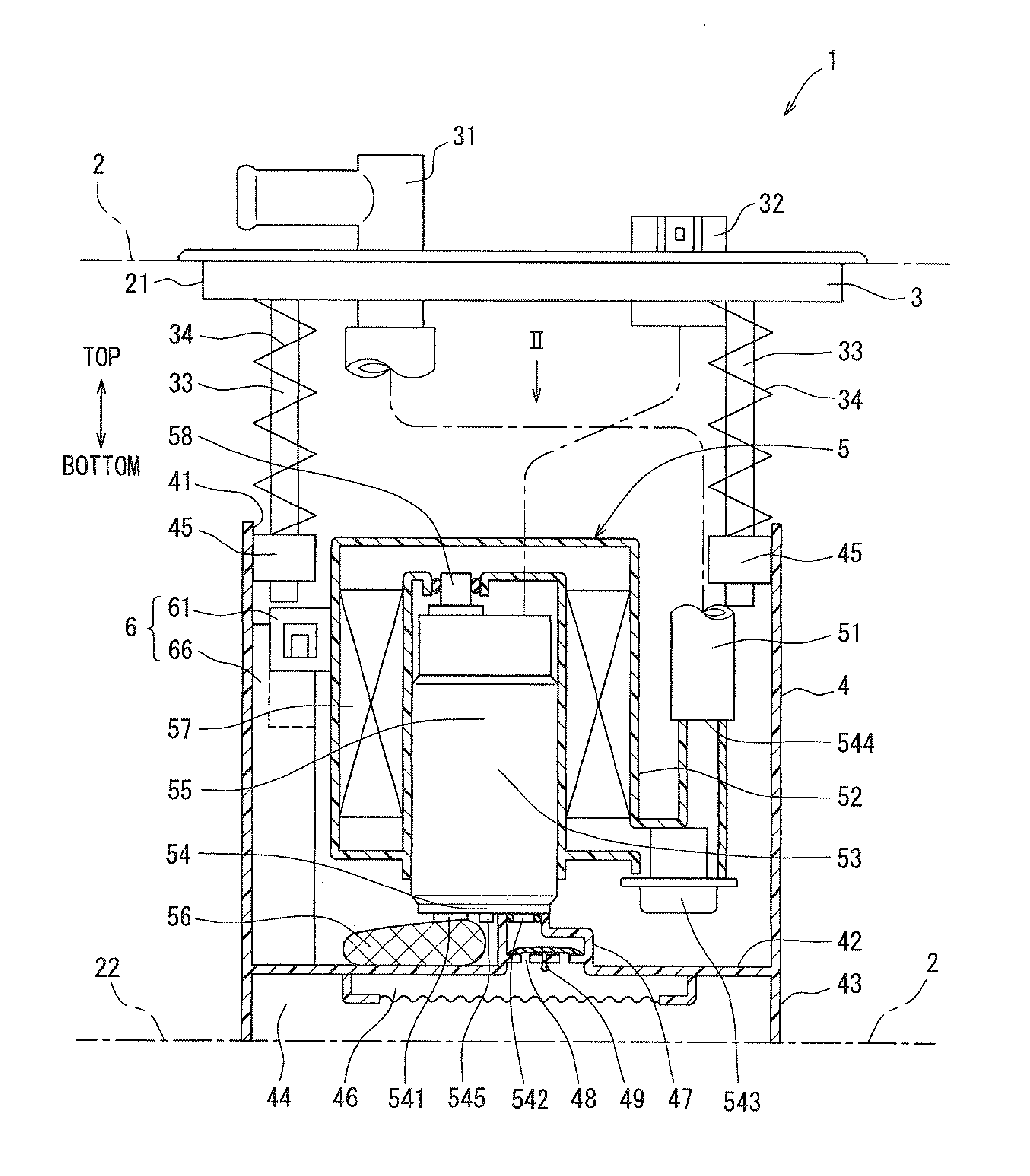
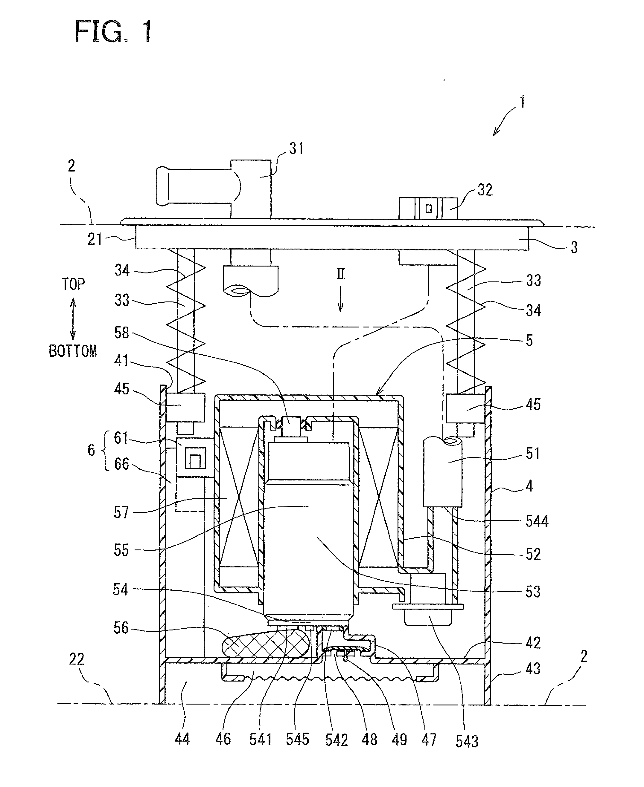
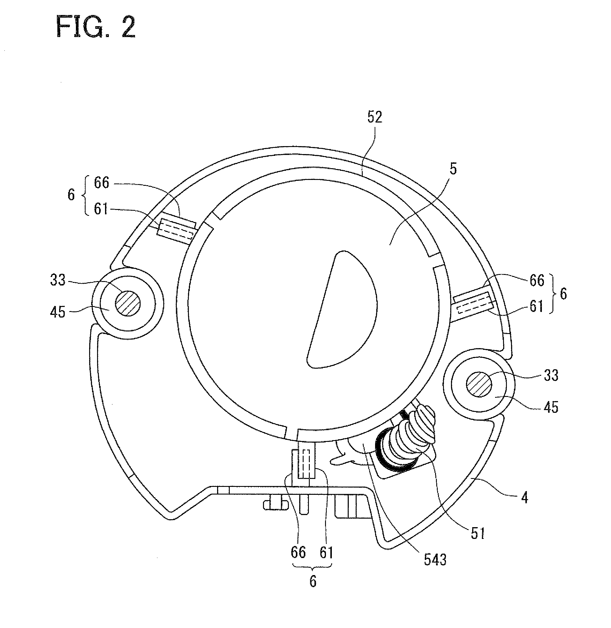
[0020]A first embodiment of the present invention will be described with reference to FIGS. 1 to 3. FIG. 1 shows a state where a fuel pump module 1 is disposed in a fuel tank 2. In FIG. 1, the top-bottom direction is a gravity direction of the fuel tank 2 mounted on a vehicle. The fuel pump module 1 is configured to supply fuel in the fuel tank 2 to an exterior portion of the fuel tank 2, for example, an internal combustion engine.

[0021]The fuel pump module 1 is inserted into the fuel tank 2 from an open portion 21 of the fuel tank 2, and is disposed in the fuel tank 2. The fuel pump module 1 is located on a bottom surface 22 of the fuel tank 2. A flange 3 is fitted in the open portion 21 to close the open portion 21.

[0022]The fuel pump module 1 is constructed by assembling a sub-tank 4, a pump unit 5, and the like. The sub-tank 4 is accommodated in the fuel tank 2, and the pump unit 5 is located in the sub-tank 4. The flange 3 and the sub-tank 4 are coupled to each other by using s...

second embodiment

[0048]A second embodiment of the present invention will be described with reference to FIG. 4. FIG. 4 shows a guide member 6a of a fuel pump module 1a in a state before the pump unit 5 is assembled to the sub-tank 4. As shown in FIG. 4, the guide member 6a includes a held portion 611 formed at the case 52 of the pump unit 5, and a holding portion 661 formed at the sub-tank 4. The held portion 611 extends radially from the side wall of the case 52 of the pump unit 5 toward the inner wall of the sub-tank 4. The held portion 611 includes a base portion 621, an insertion portion 631 and an engagement hole portion 651. The base portion 621 is held by the side wall of the case 52 at one end, and extends radially outwardly toward the inner wall of the sub-tank 4. The insertion plate 631 extends downwardly from the other end of the base portion 621, and the engagement hole portion 651 is located to be spaced from the insertion plate 631 by a predetermined distance at a position radially out...


PUM

PropertyMeasurementUnit
movementaaaaaaaaaa
gravityaaaaaaaaaa
circular shapeaaaaaaaaaa

Abstract

A fuel pump module includes a cylindrical sub-tank having an open portion at one end and a bottom portion at the other end, and a fuel pump located in the sub-tank. The bottom portion of the sub-tank is provided with an introducing passage from which fuel is introduced into the sub-tank, and a bottom portion of the fuel pump is provided with a suction port through which the fuel outside of the sub-tank is drawn into the sub-tank In the fuel pump module, a guide member is provided in at least one of the sub-tank and the fuel pump to guide the suction port of the fuel pump to the introducing passage of the sub-tank when the fuel pump is inserted from the open portion of the sub-tank toward the bottom portion of the sub-tank and is assembled to the sub-tank.

Description

CROSS REFERENCE TO RELATED APPLICATION[0001]This application is based on Japanese Patent Application No. 2007-025941 filed on Feb. 5, 2007, the contents of which are incorporated herein by reference in its entirety.BACKGROUND OF THE INVENTION[0002]1. Field of the Invention[0003]The present invention relates to a fuel pump module, and a method of producing the fuel pump module.[0004]2. Description of the Related Art[0005]U.S. Pat. No. 5,596,970 describes a fuel pump module that can stably supply fuel even when a residual amount of fuel in a fuel tank is reduced. The fuel pump module has a sub-tank for accommodating a fuel pump. The fuel pump supplies the fuel in the sub-tank to an internal combustion engine while drawing the fuel of the fuel tank into the sub-tank. A bottom portion of the fuel pump is provided with a first suction port for drawing the fuel within the sub-tank, and a second suction port for drawing the fuel outside of the sub-tank. The second suction port is formed to...

Claims


Application Information

Patent Timeline
Patent Type & Authority Applications(United States)
IPC IPC(8): F02M37/04
CPCF02M37/103Y10T29/49236F02M37/106
Inventor IGARASHI, RYUJIYAMADA, KATSUHISA
Owner DENSO CORP
Why Eureka
Try Eureka