
Processor capping method in virtual machine system

Inactive Publication Date: 2008-07-31
HITACHI LTD
View PDF7 Cites 27 Cited by
  • Summary
  • Abstract
  • Description
  • Claims
  • Application Information

AI Technical Summary

Benefits of technology

[0017]An object of the present invention is to draw up and carry out an unbiased schedule of a processor capping enabled virtual machine for a physical processor within a range in which the processor utilization rate of the virtual machine does not exceed a service rate designated by a user even when a virtual machine standing idle is active.
[0018]Another object of the present invention is to realize a processor capping method in which the processing time does not depend on either the number of virtual machines configured in the virtual machine system or the number of virtual processors each of the virtual machines has.

Problems solved by technology

The value of unit processor time is set as being sufficiently larger than a time slice and therefore, if the processor capping enabled virtual machine is conditioned to stand busy while the other of all virtual machines standing idle, the VMM continuously schedules virtual processors of the virtual machine for a physical processor, with the result that the utilization processor time of the virtual machine immediately reaches the possessive processor time of the virtual processor, thus performing limitation by the processor capping, and the schedule of the virtual machine for the physical computer is prevented until the utilization processor time is reset, eventually raising a problem that the schedule of the processor capping enabled virtual machine is extensively biased.

Method used


Image

  • Processor capping method in virtual machine system
  • Processor capping method in virtual machine system
  • Processor capping method in virtual machine system

Examples


Embodiment Construction

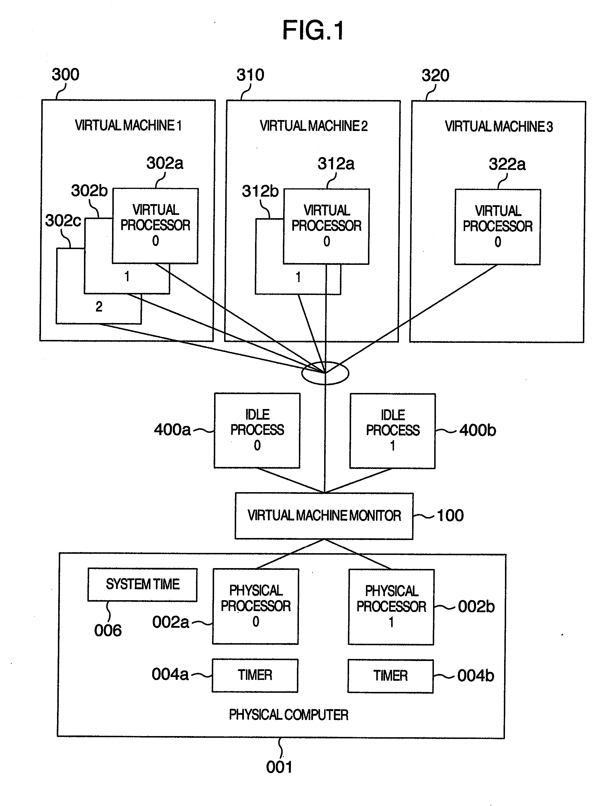
[0035]An embodiment to which the present invention is applied will be detailed with reference to the accompanying drawings.

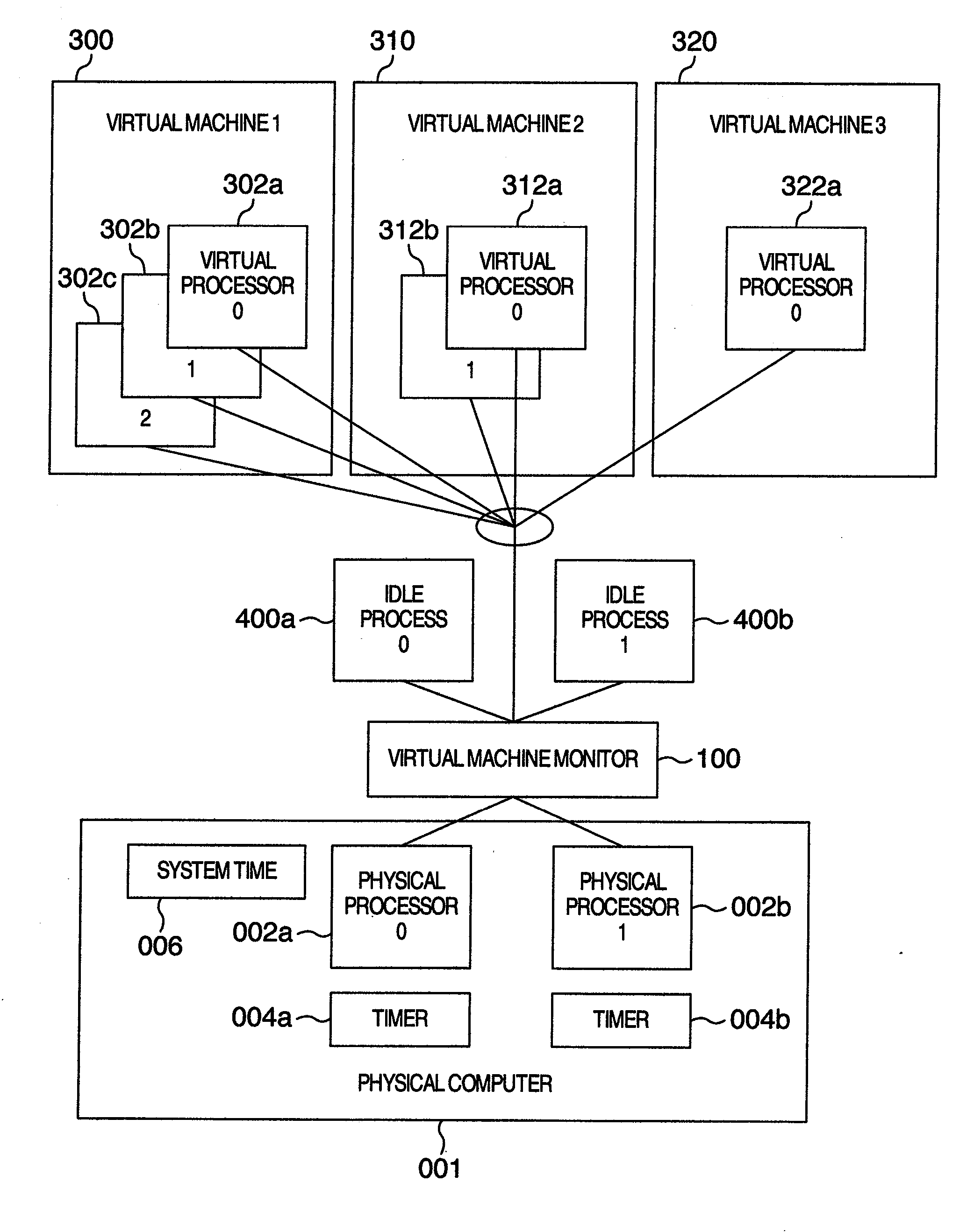
[0036]Referring to FIG. 1, a virtual machine system to which the present invention is applied is configured as diagrammatically outlined therein.

[0037]A physical computer 001 includes a physical processor 0002a, a physical processor 1002b, a system time 006 and timers 004a and 004b associated with the physical processors 0002a and 1002b, respectively.

[0038]In the present embodiment, the number of the physical processors is two but the present invention in no way limits the number of physical processors and can be applicable to a physical computer having one or more arbitrary number of physical processors.

[0039]The system time 006 is a time common to all of the physical processors and is consulted by a virtual machine monitor (VMM) 100 for the sake of measuring a physical processor time and warranting that the physical computer 001 alone or cooperative with the V...


PUM


Abstract

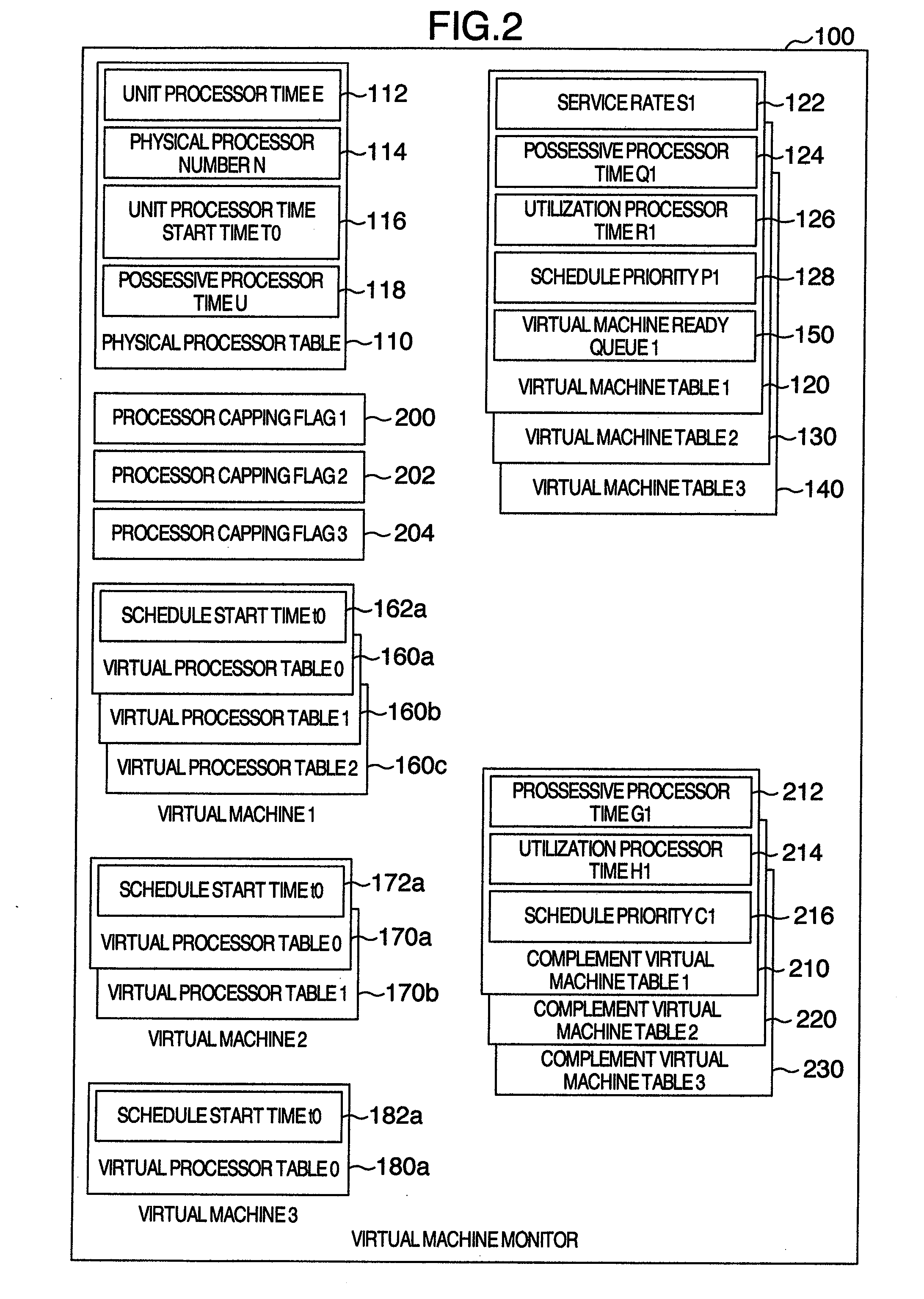
In a processor capping method in a virtual machine system, a complement virtual machine is created having a possessive processor time equal to the difference of subtraction of a possessive processor time given to the processor capping enabled virtual machine from a possessive processor time of the whole physical computer; a processor time by which each virtual machine utilizes the physical processor per unit time is determined; schedule priorities of each virtual machine and of the complement virtual machine are determined on the basis of their possessive processor times and the determined utilization processor time as well; and the schedule priority of the processor capping enabled virtual machine is compared with that of the complement virtual machine corresponding to the processor capping enabled computer to decide whether the schedule for the physical processor of the virtual processor the processor capping enabled virtual machine has is permissible or prohibitive.

Description

INCORPORATION BY REFERENCE[0001]The present application claims priority from Japanese application JP2007-018668 filed on Jan. 30, 2007, the content of which is hereby incorporated by reference into this application.BACKGROUND OF THE INVENTION[0002]The present invention relates to a virtual machine system and more particularly, to a method for causing a virtual machine monitor to control the schedule of a virtual machine and a virtual processor which the virtual machine has on the basis of a schedule priority.[0003]As a standardized use of a physical computer comprised of a plurality of processors prevails and the technology develops, high multiplexing of processors has been advancing. In the future, the importance of a virtual machine system using a physical computer comprised of a plurality of processors and of a virtual machine system for configuring a virtual machine comprised of a plurality of virtual processors as well is expected to increase.[0004]Some of virtual machine syste...

Claims


Application Information

Patent Timeline
IPC IPC(8): G06F9/455
CPCG06F9/45533Y02B60/142G06F2209/504G06F9/5077Y02D10/00
Inventor MATSUMOTO, SHUHEIINOUE, HIRONORISHINOHARA, MAKIKOHAYAKAWA, NORIMITSU
Owner HITACHI LTD
Learn More