
Method and system for protecting signaling information

a signaling information and protection technology, applied in the field of mobile radio access networks, can solve problems such as s1-u interface without integrity or confidentiality protection at all, and channel which lacks protection,

Inactive Publication Date: 2008-07-31
TELEFON AB LM ERICSSON (PUBL)
View PDF3 Cites 44 Cited by
  • Summary
  • Abstract
  • Description
  • Claims
  • Application Information

AI Technical Summary

Benefits of technology

[0028]According to a first embodiment the UE provides the AP with a fresh integrity key over an already existing and secure channel for enabling AP to integrity protect information sent to the UPN.

Problems solved by technology

For this reason, totally new, optimized signaling flows will be used, raising some problems from a security point of view.
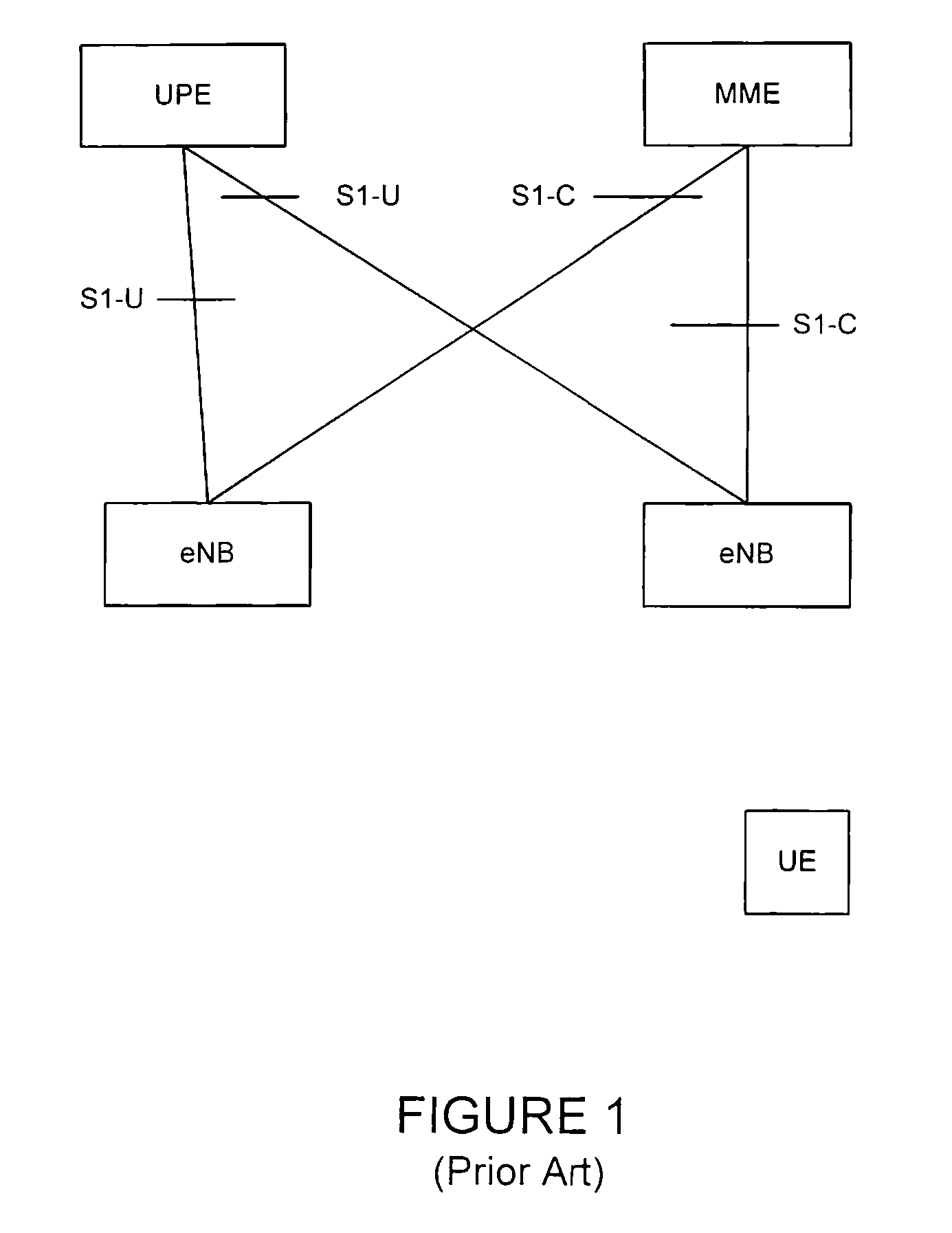
The S1-U interface at the time was not considered important enough, so the S1-U interface has no integrity or confidentiality protection at all.
The fact that a control plane message is sent over a user plane “channel”, i.e., a channel which lacks protection, is disadvantageous from a security point of view.
The effect is that the UPE directs the traffic to an IP address and port specified by the attacker.The S1-U interface does necessarily provide reliable transport, i.e., packets can be lost.
An alternative would be to generate multiple tokens at UE that is disadvantageous.
A problem with using ACK is that this signal too has to be integrity protected or an attacker can stop UPE from receiving the path switch message and spoof an ACK message to the eNB.
However, certain problems generally relate to networks providing connectivity for mobile terminals.
Specifically, the problem discussed above stems from the need to perform mobility related control plane signaling aiming to redirect user plane traffic in a network having (physically) separated nodes for user plane and control plane traffic, respectively.
Therefore it is likely that future (mobile) network architectures will to a large extent adopt the same principles and consequently, such future networks are likely to encounter the same problems related to protection of the mobility related signaling.

Method used


Image

  • Method and system for protecting signaling information
  • Method and system for protecting signaling information
  • Method and system for protecting signaling information

Examples


first embodiment

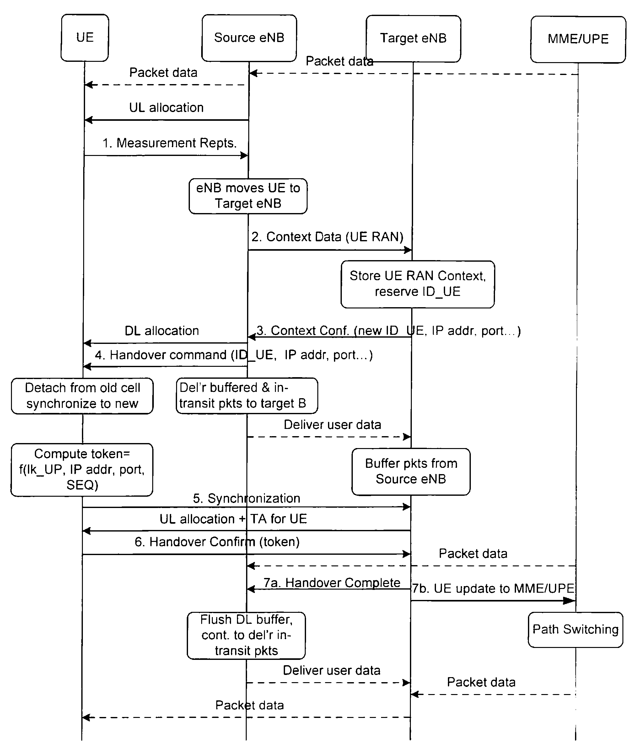
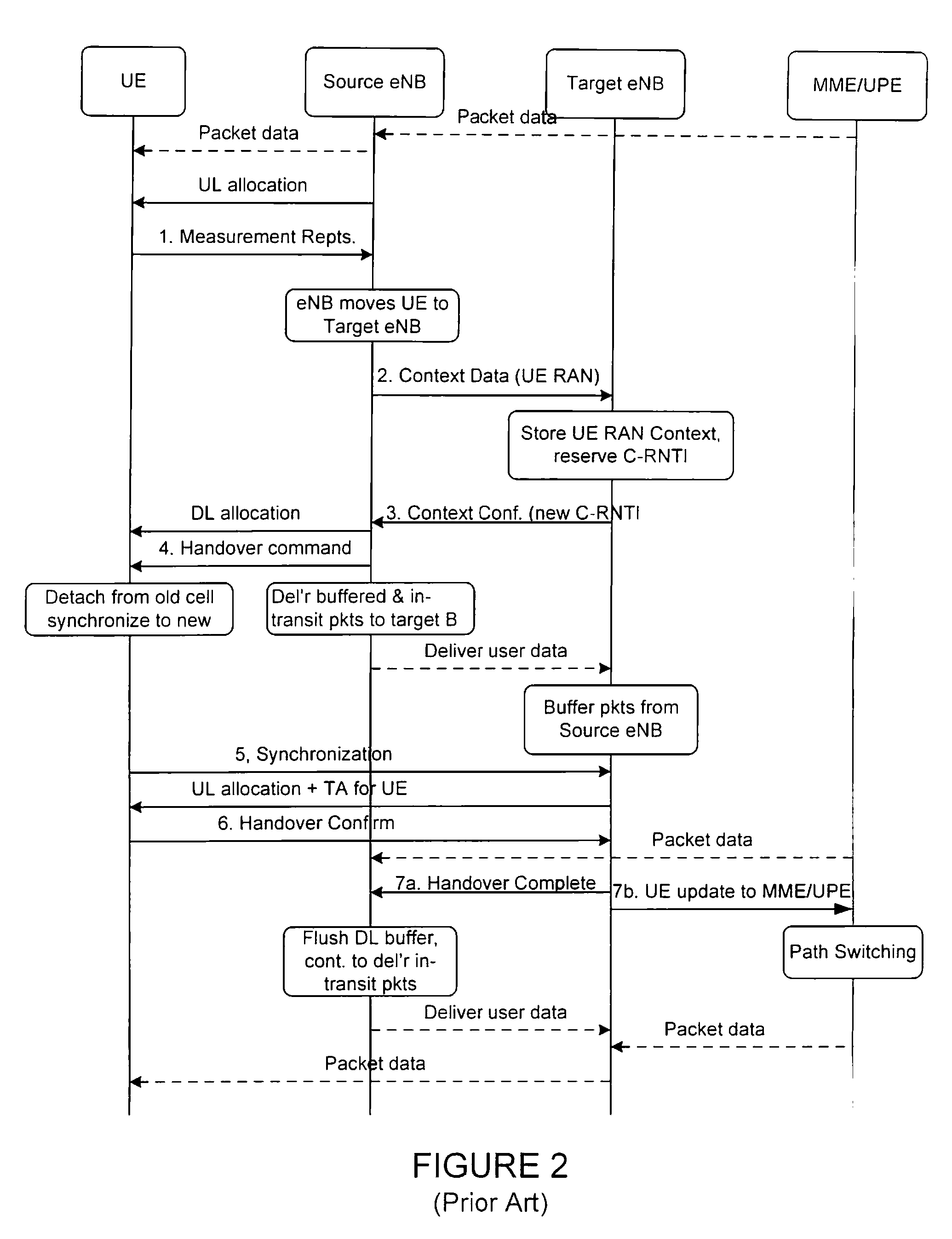
[0047]FIG. 3 depicts a high level signaling diagram of handover according to the present invention. The figure only shows the relevant changes to the prior art signaling diagram shown in FIG. 2. The steps involved in the process are as follows:

[0048]1. When UE 302 is about to send the handover confirm message to the target AP, it generates a fresh integrity key K3 by applying a Key Derivation Function (KDF) with the key K1, a sequence number (or other nonce) and possibly some other data as input (e.g., UE identity). This step may also be prepared in advance.

[0049]2. UE 302 then delivers the integrity key K3 and the sequence number to target AP 304 over the secure channel protected with K2. This can suitably be done in the handover confirm message. Note that target AP 304 can verify the integrity of the key K3 due to the protection provided by K2. Target AP 304 can, assuming encryption is used, also be sure that no unauthorized 3rd party has the same key.

[0050]3. Target AP 304 uses t...

second embodiment

[0053]FIG. 4 illustrates a high level signaling diagram of handover according to the present invention. The figure only shows the relevant changes to the prior art signaling diagram shown in FIG. 2. The steps involved in the process are as follows:

[0054]1. During the authentication process of UE, wherein key derivations are done, CPN 408 provides UPN 404 with the K2 key (this key is also provided to the AP).

[0055]2. UE 402 sends a handover confirm message to Target AP 402

[0056]3. Target AP 404 uses the K2 key to integrity protect the path switch message, containing the information from Target AP 404 and possible information from the handover command from UE 402, to UPN 406. That is, the key K2, normally used only between UE 402 and Target AP 404, are, according to this embodiment, re-used also between Target AP 404 and UPN 406.

[0057]4. UPN 406 can now verify integrity of the path switch message.

[0058]It is good cryptographic practice to ensure that it is not possible to capture mess...

third embodiment

[0060]FIG. 5 depicts a high level signaling diagram of handover according to the present invention:

[0061]1. Target AP 506 includes address and port, allocated for reception of data from UE 502, in the message providing Source AP 504 and ID_UE.

[0062]2. Source AP 504 sends, over the connection that is (integrity and confidentiality) protected using K2, the address port information to UE 502 together with ID_U E.

[0063]3. UE 502 includes the address and port information in the creation of a token thereby binding the information that Target AP 504 sends to UPN 508.

[0064]4. UE 502 sends the token to Target AP 504 in a handover confirm message.

[0065]5. Target AP 504 includes the token in the path switch message sent to UPN 508, which can verify the integrity of the token, and can rest assured that the address of Target AP 504 is the correct one.

[0066]A clear distinction is noticed between the identity of an AP as used in the prior art solution and the address of AP as used in the third emb...


PUM


Abstract

A path switch message in a mobile radio access network is protected as the message is sent over a user plane interface that may be insecure (e.g. lacks integrity and / or confidentiality protection). According to the invention a UE provides an AP with a fresh integrity key over an already existing and secure RAN channel enabling AP to use the integrity key to integrity protect information sent to a UPN. Specifically, UE derives locally at least a user plane key K1. The key derivation is done at authentication e.g. when performing an AKA procedure. On the network side CPN derives the same key K1 for delivery to UPN. At handover, the UE generates a fresh integrity key K3 by applying a Key Derivation Function (KDF) with at least the UP key K1 and a nonce, e.g. a sequence number.

Description

CROSS-REFERENCE TO RELATED APPLICATIONS[0001]This application which claims the benefit of U.S. Provisional Application No. 60 / 886,694, filed Jan. 26, 2007, the disclosure of which is incorporated herein by reference.STATEMENT REGARDING FEDERALLY SPONSORED RESEARCH OR DEVELOPMENT[0002]NOT APPLICABLEREFERENCE TO SEQUENCE LISTING, A TABLE. OR A COMPUTER PROGRAM LISTING COMPACT DISC APPENDIX[0003]NOT APPLICABLEBACKGROUND OF THE INVENTION[0004]The present invention relates to mobility in Radio Access Networks. More particularly, and not by way of limitation, the present invention is directed to a system and method for providing additional protection of mobility signaling messages in a wireless network.[0005]3GPP is currently standardizing EPS; the Evolved Packet System. the recently renamed System Architecture Evolution (SAE). 3GPP is also developing standards and definition of a new Orthogonal Frequency Division Multiplexing Access (air interface) through the Long Term Evolution program...

Claims


Application Information

Patent Timeline
Patent Type & Authority Applications(United States)
IPC IPC(8): H04L9/08
CPCH04J11/0069H04L63/061H04L63/12H04W12/04H04L2209/80H04L9/0844H04L9/0861H04L9/3242H04W12/10H04L2463/061H04W36/0038H04W12/041H04W12/106
Inventor NORRMAN, KARLNASLUND, MATS
Owner TELEFON AB LM ERICSSON (PUBL)
Learn More