Heat transfer apparatus and method

a technology of heat exchange apparatus and heat exchange method, which is applied in the direction of lighting and heating apparatus, water supply installation, instruments, etc., can solve the problems of not being able to be easily accessible and adjusted, and achieve the effect of improving heat exchange efficiency, more efficient heat transfer, and improving heat transfer efficiency

Inactive Publication Date: 2008-07-31
BRADLEY UNIVERSITY
View PDF57 Cites 2 Cited by
  • Summary
  • Abstract
  • Description
  • Claims
  • Application Information

AI Technical Summary

Benefits of technology

[0011]Objects of the instant invention are accomplished through the use of a heat transfer apparatus comprising a manifold and a plurality of tubes extending from the manifold. In a preferred embodiment, the manifold comprises an inlet and a plurality of mini heat exchanger channels connected to the inlet, wherein each mini heat exchanger channel is operably connected to a tube. In a preferred embodiment at least one tube comprises a fluid flow restrictor. In other preferred embodiments, each of the tubes includes a fluid flow restrictor. The fluid flow restrictors of the instant invention are not limited to a particular means or structure, but non-limiting examples in some configurations include: a tube restrictor valve; a tube crimp or a restriction tube segment (such as a reducer coupler, wherein the restriction tube segment has an inside diameter smaller than the inside diameter of a tube with no fluid flow restrictor). The instant invention allows the flow of fluid to be more evenly distributed among the plurality of tubes than a heat transfer apparatus with no fluid flow restrictor. If each of the tubes of the instant invention are restricted to its respective preferred predetermined amount, the flow of fluid is generally evenly distributed among the tubes, resulting in a more efficient transfer of heat. In preferred embodiments, the flow of fluid is about equally distributed among the tubes. In preferred embodiments, the fluid is liquid, vapor or some combination of both liquid and vapor. In some embodiments, the fluid is a refrigerant.
[0012]Objects of the instant invention are also accomplished through a method of improving the efficiency of heat transfer comprising restricting the flow of fluid in at least one tube of a heat transfer apparatus to a predetermined amount. In some embodiments of the instant invention the predetermined amount of flow is a function of the position of the tube along the manifold relative to a fluid inlet position of the manifold. In some embodiments, the flow of fluid is restricted in each of the tubes of the heat transfer apparatus. The restriction of fluid flow is not limited to a particular method, means or structure, but non-limiting examples in some configurations include, restricting fluid flow using a tube restrictor valve, a tube crimp or a restriction tube segment (such as a reducer coupler, wherein the restriction tube segment has an inside diameter smaller than the inside diameter of a tube with no fluid flow restrictor). If only one of the tubes of the instant invention is restricted, it allows the flow of fluid to be more evenly distributed among the plurality of tubes than a heat transfer apparatus with no fluid flow restrictor. If each of the tubes of the instant invention are restricted to its respective preferred predetermined amount, the flow of fluid is generally evenly distributed among the tubes, resulting in a more efficient transfer of heat. In preferred embodiments, the flow of fluid is about equally distributed among the tubes. In preferred embodiments the fluid is liquid, vapor or some combination of both liquid and vapor. In some embodiments, the fluid is a refrigerant.
[0013]Objects of the instant invention are also accomplished through a method of modeling the optimization of heat transfer efficiency of a two-phase heat transfer apparatus, the apparatus comprising a manifold and a plurality of tubes extending from the manifold. The method includes the steps of estimating sudden expansion two-phase pressure drop at an inlet of the manifold; predicting the two-phase pressure drop across tubes of the manifold; determining parameters for each tube of the apparatus related to an uneven fluid flow distribution; determining parameters for each tube related to an even flow distribution; and determining a preferable restriction cross-sectional area of each tube. In some embodiments, the apparatus further comprises a fluid flow restrictor connected to at least one of the plurality of tubes, and the method further comprises the steps of calibrating a dimensionless position of each fluid flow restrictor to a restriction cross-sectional area of each respective tube; and determining zero offset values. In some embodiments, the method further comprises restricting the cross-sectional area of at least one tube to the preferable restriction cross-sectional area. In other embodiments, the method further comprises restricting the cross-sectional area of each tube to each tube's respective preferable restriction cross-sectional area. The restriction of fluid flow is not limited to a particular method, means or structure, but non-limiting examples in some configurations include, restricting fluid flow using a tube restrictor valve, a tube crimp or a restriction tube segment (such as a reducer coupler, wherein the restriction tube segment has an inside diameter smaller than the inside diameter of a tube with no fluid flow restrictor). If only one of the tubes of the instant invention is restricted, it allows the flow of fluid to be more evenly distributed among the plurality of tubes than a heat transfer apparatus with no fluid flow restrictor. If each of the tubes of the instant invention are restricted to its respective preferred predetermined amount, the flow of fluid is generally evenly distributed among the tubes, resulting in a more efficient transfer of heat. In preferred embodiments, the flow of fluid is about equally distributed among the tubes. In preferred embodiments the fluid is liquid, vapor or some combination of both liquid and vapor. In some embodiments, the fluid is a refrigerant.

Problems solved by technology

One disadvantage to inserting flow distribution plates into the manifold is that it does not allow for easy access and adjustment over the course of time and usage.

Method used


Image

  • Heat transfer apparatus and method
  • Heat transfer apparatus and method
  • Heat transfer apparatus and method

Examples


Embodiment Construction

[0029]As required, several detailed embodiments of the present inventive concept are disclosed herein; however, it is to be understood that the disclosed embodiments are merely exemplary of the principles of the inventive concept, which may be embodied in various forms. Therefore, specific structural and functional details disclosed herein are not to be interpreted as limiting, but merely as a basis for the claims and as a representative basis for teaching one skilled in the art to variously employ the present inventive concept in virtually any appropriately detailed structure.

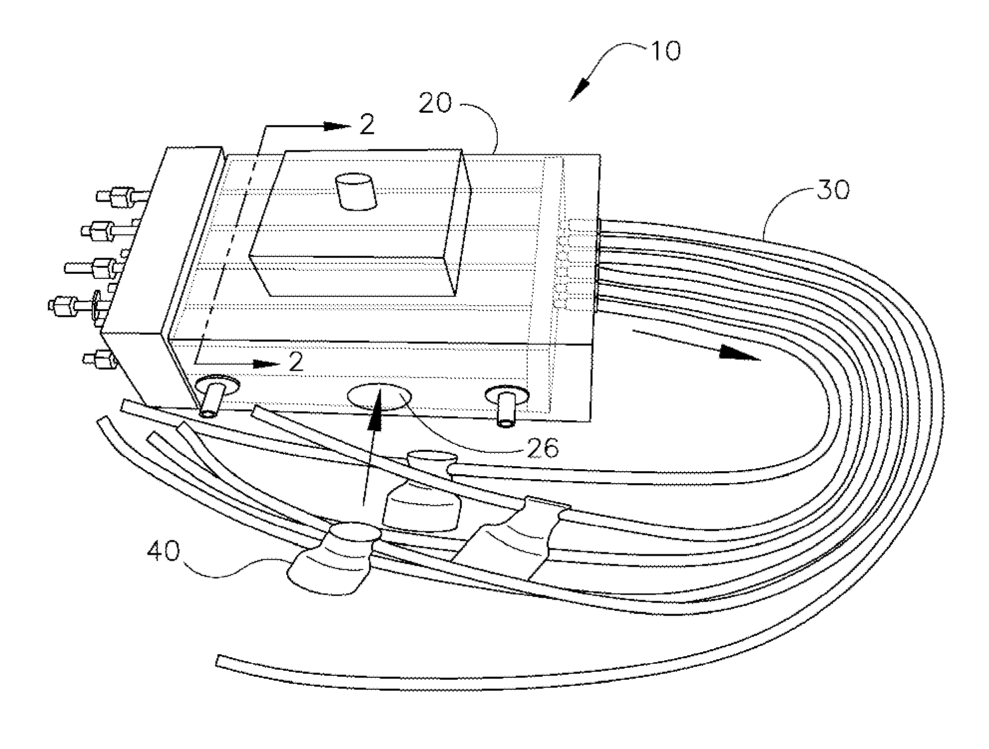
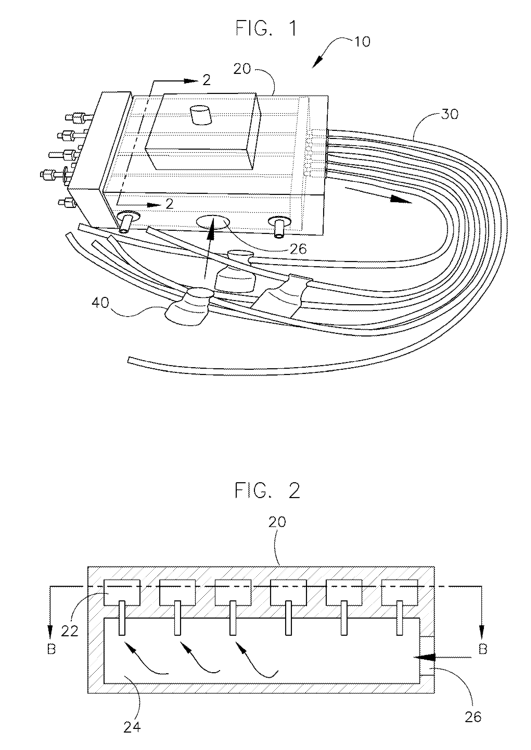
[0030]Referring to FIG. 1, a heat transfer apparatus of one embodiment of the instant invention is shown. The apparatus of FIG. 1 includes a manifold and six tubes extending from the manifold. Some of the tubes include a tube restrictor valve.

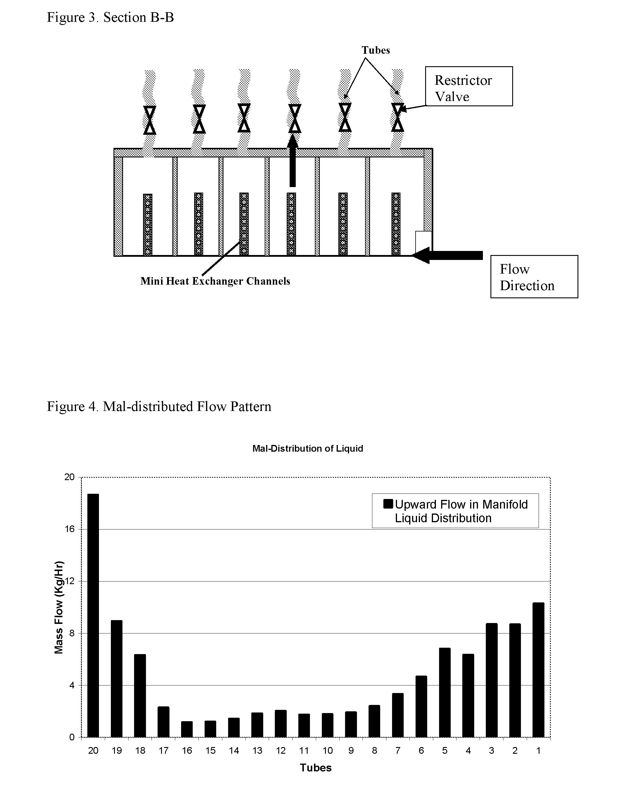
[0031]Restricting the tubes improves the uniformity of the mass distribution between heat exchanger tubes. This was demonstrated experimentally as is discussed in further...


PUM


Abstract

A method to optimize fluid flow distribution in two-phase heat exchange systems is provided. Also provided is a heat transfer device and method that incorporate restricted flow tubes to optimize fluid flow in two-phase systems.

Description

CROSS-REFERENCE TO RELATED APPLICATIONS[0001]This application claims priority pursuant to 35 U.S.C. 119(e) to co-pending U.S. Provisional Patent Application Ser. No. 60 / 898,337, filed Jan. 30, 2007, the entire disclosure of which is incorporated herein by reference.FIELD OF THE INVENTION[0002]The present invention relates generally to heat exchange systems. More specifically, the present invention is concerned with (1) methods to optimize flow in two-phase heat exchange systems and (2) devices and methods that incorporate restricted flow tubes to optimize even fluid flow in two-phase systems.BACKGROUND OF THE INVENTIONReferences[0003]The following references are cited by number throughout this disclosure and provide general background information. Applicant makes no statement, inferred or direct, regarding the status of these references as prior art. Applicant reserves the right to challenge the veracity of statements made in these references, which are incorporated herein by refere...

Claims


Application Information

Patent Timeline
Patent Type & Authority Applications(United States)
IPC IPC(8): F28F9/02F17D1/20G06G7/50
CPCF17D1/005G06F17/5009F28F1/00F28F9/0275Y10T137/0324Y10T137/87877F25B39/028F28D1/05316F28D3/02F28D3/04G06F30/20
Inventor SEELI, JOHN W.ZIETLOW, DAVID
Owner BRADLEY UNIVERSITY
Why Eureka
Try Eureka