
Disk failure restoration method and disk array apparatus

a technology of disk array and failure restoration method, which is applied in the direction of error detection/correction, redundant hardware error correction, instruments, etc., can solve the problems of reducing the response time of input and output to and from the host, processing time end up taking time, and increasing the processing time for transferring large amount of data. , to achieve the effect of shortening the processing tim

Inactive Publication Date: 2008-07-24
FUJITSU LTD
View PDF6 Cites 218 Cited by
  • Summary
  • Abstract
  • Description
  • Claims
  • Application Information

AI Technical Summary

Benefits of technology

[0015]An object of the present invention, in consideration of the above problem, is to provide a method of restoration from failure of a disk of a disk array apparatus which can shorten the processing time for reconfiguring a RAID without changing the positions of the disks in the RAID.
[0021]The present invention can shorten the processing time for reconfiguring a RAID without changing the positions of the disks in the RAID.

Problems solved by technology

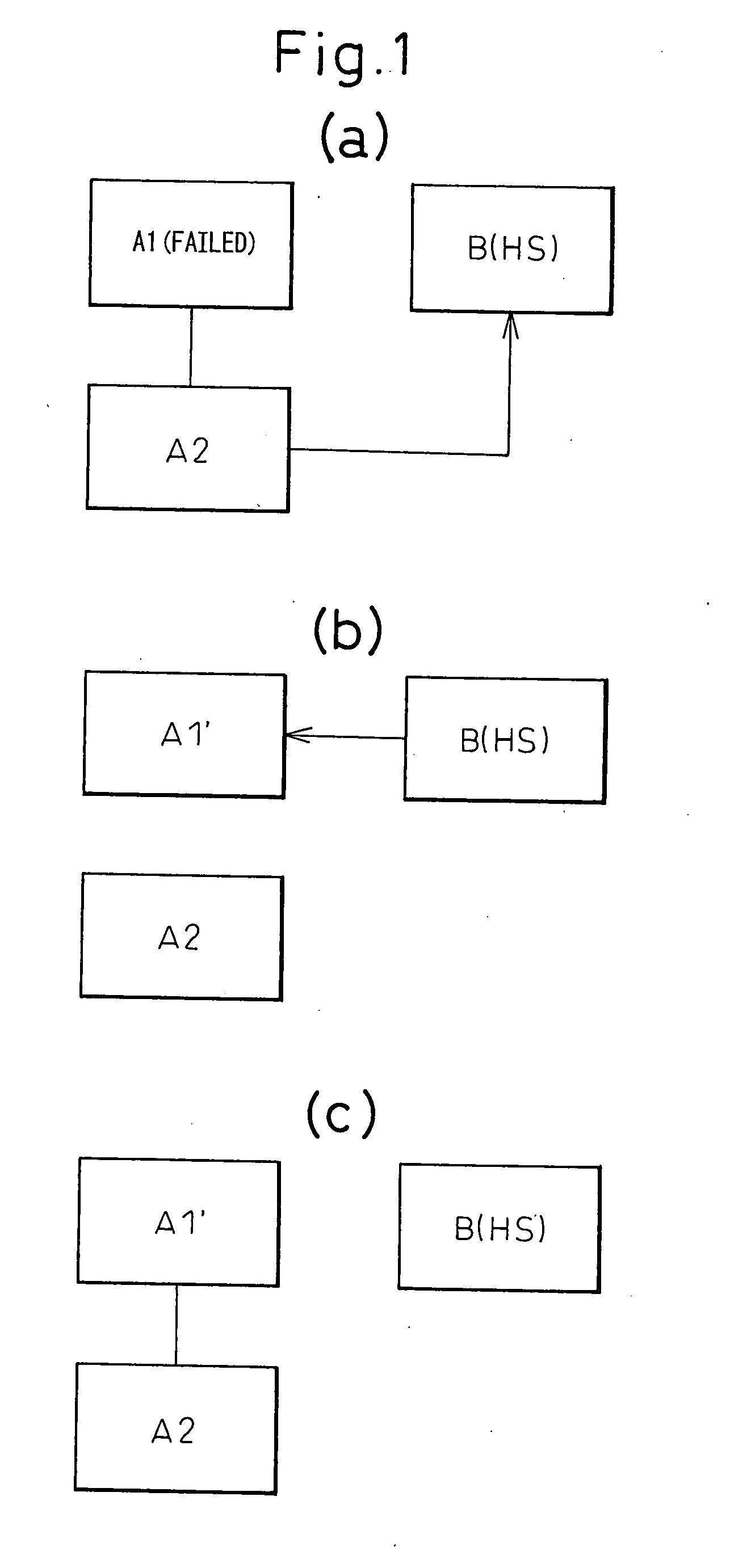
However, in the conventional processing, the data is copied twice (from the disk A2 to the disk B and from the disk B to the disk A1′), so the processing ends up taking time.
Therefore, the processing time for transferring the large amount of data also increases.
Further, during transfer of data, the response for input and output to and from the host drops and the danger of double failure increases.
However, the physical positions of the disks forming a RAID pair will end up shifting, so it will become difficult to determine later which disks are paired and therefore there will be a problem in management.

Method used


Image

  • Disk failure restoration method and disk array apparatus
  • Disk failure restoration method and disk array apparatus
  • Disk failure restoration method and disk array apparatus

Examples


first embodiment

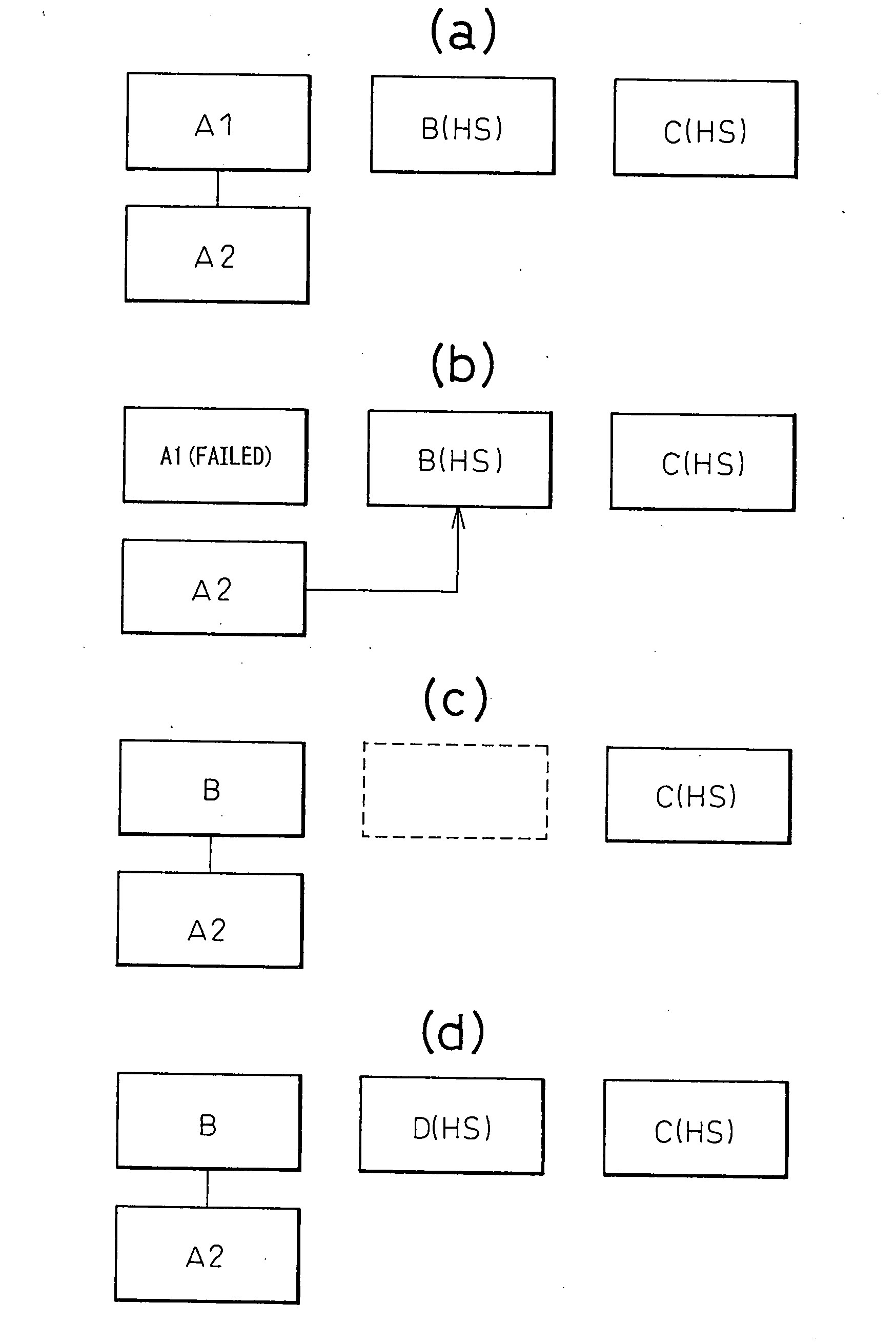
[0038]FIG. 4 schematically shows application to the RAID1. Among the large number of pairs of hard disks forming the RAID1, the disks A1 and A2 are shown. As spare disks, that is, hot spares, the disks B and C are shown.

[0039]As shown in FIG. 4(a), before a failure occurs, the disk A1 and disk A2 form a RAID1 pair and the two have the same data written in them. If the disk A1 fails, as shown in FIG. 1(b), data is copied to the spare disk B from the normal disk A2 for the transfer of data. When the transfer of data finishes, the data is duplexed by the disk A2 and disk B and the RAID1 redundancy is rebuilt. This work is generally called “rebuilding”, but in the RAID1, the data is only copied to a spare disk.

[0040]Next, copyback processing for restoring the original state is performed. In the present embodiment, the disk B to which data has finished being transferred is physically moved to the position where the disk A1 had been inserted and is inserted there in place of the disk A1 (...

second embodiment

[0057]FIG. 5 schematically shows a second embodiment applying the present invention to the RAID5. The disks A1, A2, and A3 form the RAID5. B and C are provided as hot spares.

[0058]In the RAID5, striping is performed for the disks A1, A2, and A3, so the data and parity data are stored dispersed.

[0059]If the disk A1 fails, the data of the disk A1 is reconfigured from the disk A2 and disk A3 and rebuilt at the spare disk B (FIG. 5(a)).

[0060]Next, the disk B is separated from the disk array apparatus at the instruction of the maintenance terminal 40. Simultaneously, bit map management is started and another hot spare disk C starts to be used. The initial values of the bits of the bit map are set at “0”. A bit for a region updated in data is set at “1”. As explained above, if the region managed by 1 bit of the bit map is 8 kbytes, the entire 8 kbyte region is deemed an updated region if even part of the 8 kbytes covered is updated.

[0061]If there is data to be updated when the disk B is s...


PUM


Abstract

If a disk fails, another disk is used to rebuild the data of the failed disk on a first spare disk. When finishing being rebuilt, the first spare disk is separated from the disk array apparatus. Data to be updated while the first spare disk separated is written in another disk and managed by a bit map. The first spare disk is connected to the disk array apparatus at the position of the failed disk, then only the updated data is rebuilt on the first spare disk using another disk.

Description

CROSS REFERENCE TO RELATED APPLICATION[0001]This application is a continuation application and is based upon PCT / JP2005 / 009188, filed on May 19, 2005.BACKGROUND OF THE INVENTION[0002]1. Field of the Invention[0003]The present invention relates to a method of restoration from failure of a disk in a disk array apparatus.[0004]2. Description of the Related Art[0005]A disk array comprised of a large number of storage disks connected to a network server disperses data among a plurality of hard disks, that is, magnetic disk apparatuses, so as to simultaneously secure performance and tolerance against trouble. It is also known as a “redundant array of independent disks” (RAID).[0006]RAID is technology for managing hard disks. It is classified into several levels according to the method of allocation of data to the magnetic disks or the data redundancy, that is, the method of multiplexing. RAID, for example, includes the following levels:[0007]RAID0 divides data into block units and records...

Claims


Application Information

Patent Timeline
Patent Type & Authority Applications(United States)
IPC IPC(8): G06F11/20
CPCG06F11/1088G06F2211/1059G06F11/2094G06F11/1662
Inventor KOBAYASHI, TATSUYA
Owner FUJITSU LTD
Learn More