
Two-level structured overlay design for cluster management in a peer-to-peer network

Inactive Publication Date: 2008-07-24
XEROX CORP
View PDF39 Cites 54 Cited by
  • Summary
  • Abstract
  • Description
  • Claims
  • Application Information

AI Technical Summary

Problems solved by technology

However, since the realization of logical links depends on the underlying physical connections between nodes, ignoring differences between links can lead to poor performance.
The designs of most structured peer-to-peer overlays are flat and do not reflect the underlying physical or logical organization or grouping of nodes.
Ignoring this underlying infrastructure leads to inefficient or unwanted performance because there is no control over the communication of nodes between different groups, which is considered to be more expensive than intra-group communication.
Designs exist for hierarchical overlays that connect clusters without cluster heads, but theses designs still use converging inter-cluster paths that are potential bottlenecks and do not fully exploit locality for inter-cluster searches.

Method used


Image

  • Two-level structured overlay design for cluster management in a peer-to-peer network
  • Two-level structured overlay design for cluster management in a peer-to-peer network
  • Two-level structured overlay design for cluster management in a peer-to-peer network

Examples


Embodiment Construction

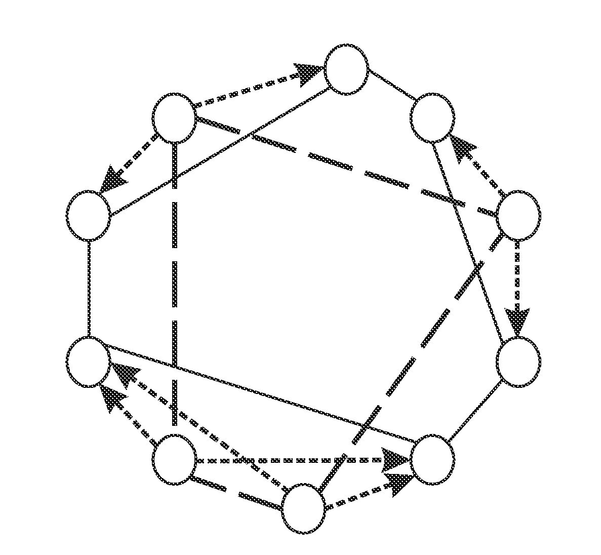
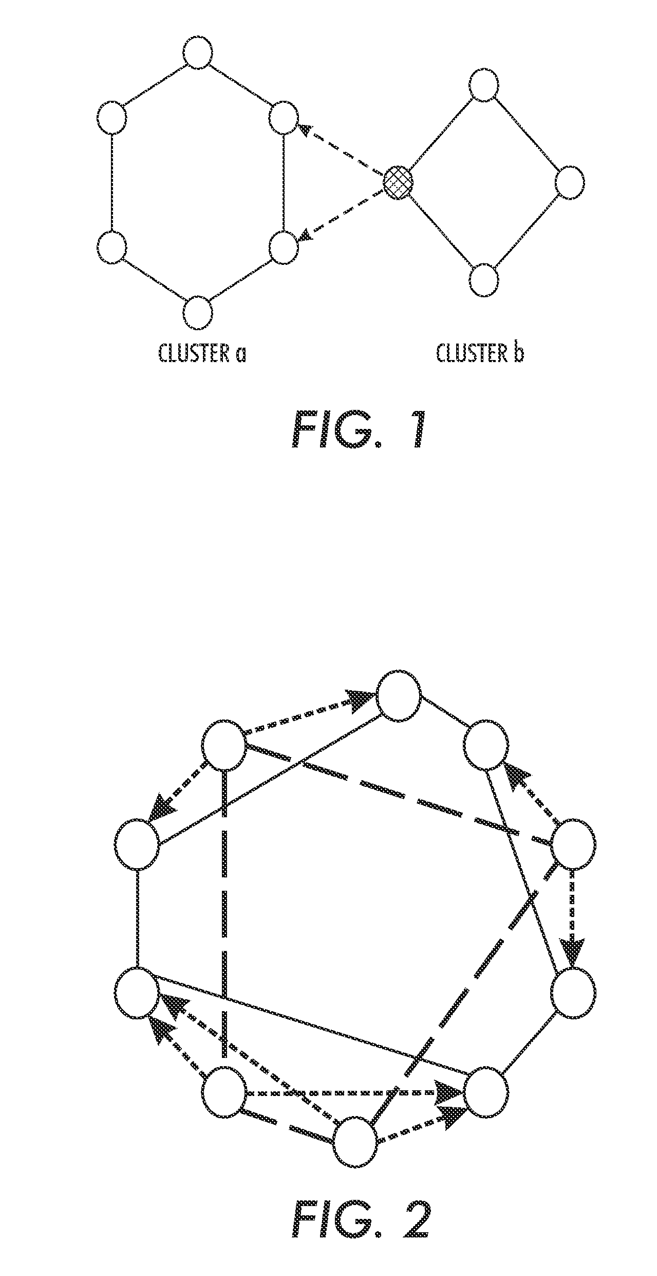
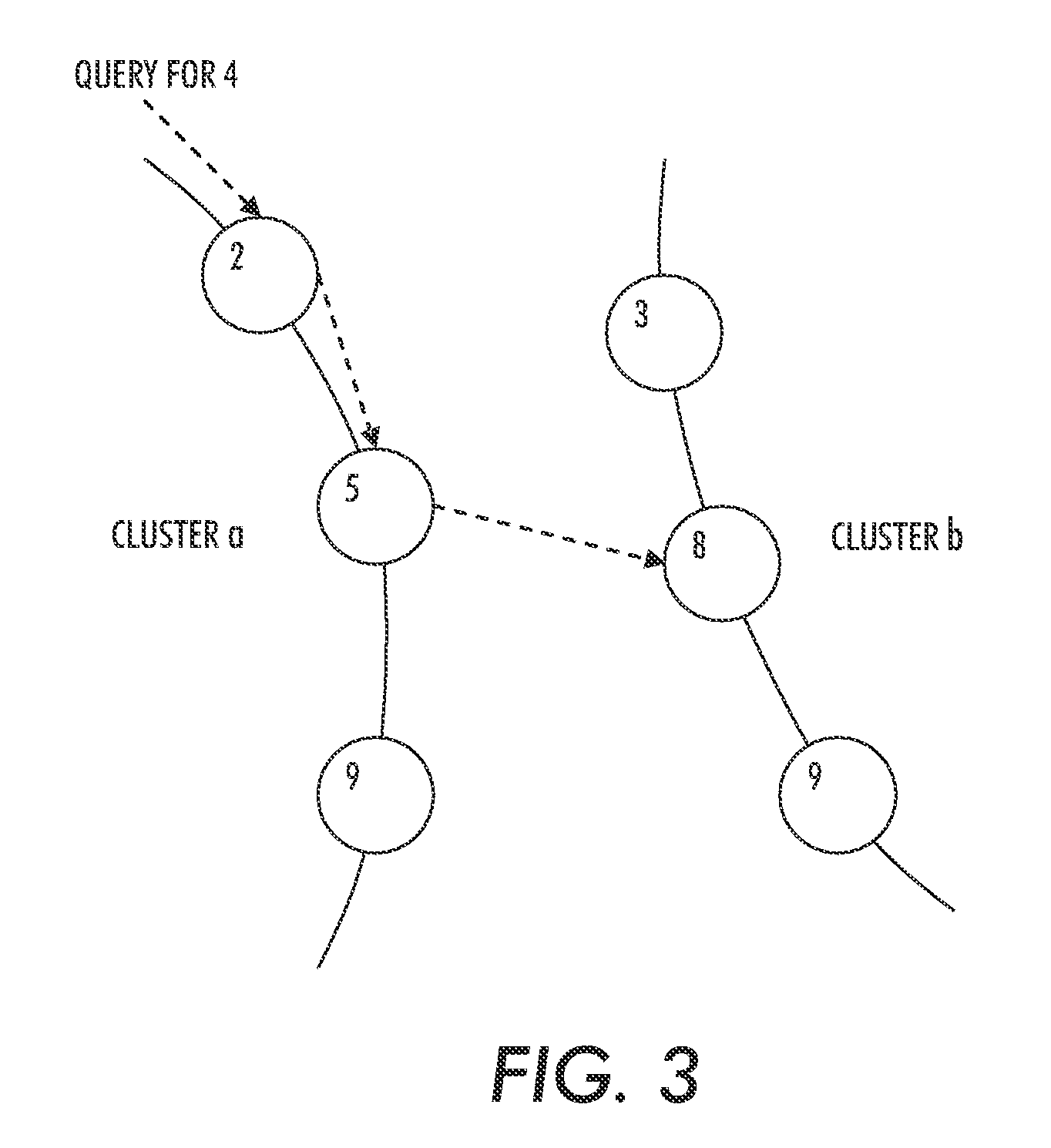
[0025]For a general understanding, reference is made to the drawings. In the drawings, like references have been used throughout to designate identical or equivalent elements. It is also noted that the drawings may not have been drawn to scale and that certain regions may have been purposely drawn disproportionately so that the features and concepts could be properly illustrated.

[0026]The description of the following example will be explained in terms of the CHORD overlay. However, any structured overlay topology lends itself to this construction. A CHORD overlay has a ring-based topology, where every node is randomly assigned an identifier in the range [0,2m). Nodes are organized in order according to their identifier to form the ring.

[0027]In a classical, single-level CHORD ring, a node joins by contacting any other node already in the overlay, from which it obtains references to its successor and predecessor in the ring, as well as a number of extra references (chords or fingers)...


PUM


Abstract

A method and system for designing file replication schemes in file sharing systems consider node storage constraints and node up / down statistics, file storage costs, and file transfer costs among the nodes, user request rates for the files, and user specified file availability requirements. Based on these considerations, a systematic method for designing file replication schemes can be implemented. The method first determines the number of copies of the files to be stored in the system to achieve the desired goal (e.g., to satisfy file availability requirements, or to maximize the system hit rate), and then selects the nodes at which to store the file copies to minimize the total expected cost. The file replication scheme for a peer-to-peer file sharing system in a distributed and adaptive manner can scale to a large number of nodes and files and can handle changes in the user request pattern over time.

Description

PRIORITY INFORMATION[0001]This application claims priority from U.S. Provisional Patent Application Ser. No. 60 / 885,951, filed on Jan. 22, 2007. The entire content of U.S. Provisional Patent Application Ser. No. 60 / 885,951, filed on Jan. 22, 2007, is hereby incorporated by reference.[0002]This application also claims priority from U.S. Provisional Patent Application Ser. No. 60 / 908,569, filed on Mar. 28, 2007. The entire content of U.S. Provisional Patent Application Ser. No. 60 / 908,569, filed on Mar. 28, 2007, is hereby incorporated by reference.BACKGROUND[0003]A network overlay is an abstraction of a physical network that identifies a subset of network nodes and maintains a set of logical links between them. The software that implements a network overlay must maintain node membership and communication, mapping the logical links to actual physical connections. In peer-to-peer overlays, all nodes participate in overlay management, maintaining a number of the logical links between th...

Claims


Application Information

Patent Timeline
IPC IPC(8): G06F17/30G06F15/16
CPCH04L67/104H04L67/1065H04L67/1053H04L45/64H04L12/4625H04L67/1059
Inventor LIN, JIENI, JIANHERNANDEZ, ANDRES QUIROZ
Owner XEROX CORP
Learn More