Eureka AIR delivers breakthrough ideas for toughest innovation challenges, trusted by R&D personnel around the world.

Liquid material vaporization apparatus for semiconductor processing apparatus

a technology of liquid material vaporization and semiconductor processing, which is applied in the direction of heating types, container discharge methods, separation processes, etc., can solve the problems of affecting affecting the flow of vaporized material (gas flow), and requiring additional control. , to achieve the effect of reducing the temperature of liquid material, effective inhibition, and reducing the thermal conductivity

Active Publication Date: 2008-07-24
ASM JAPAN
View PDF54 Cites 386 Cited by
  • Summary
  • Abstract
  • Description
  • Claims
  • Application Information

AI Technical Summary

Benefits of technology

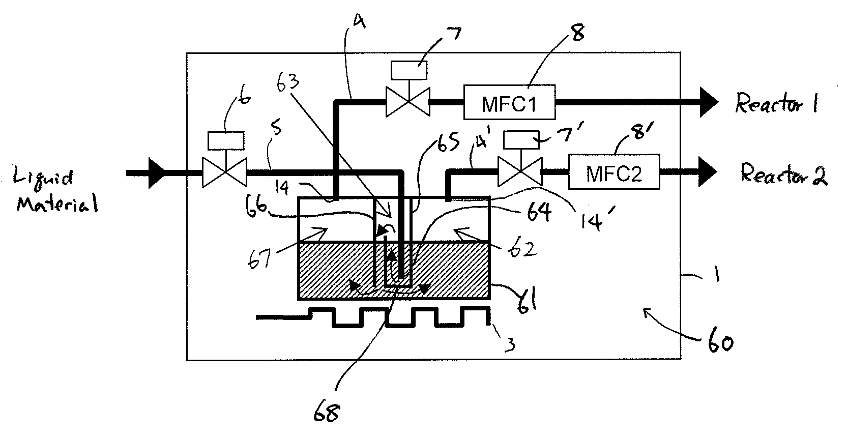
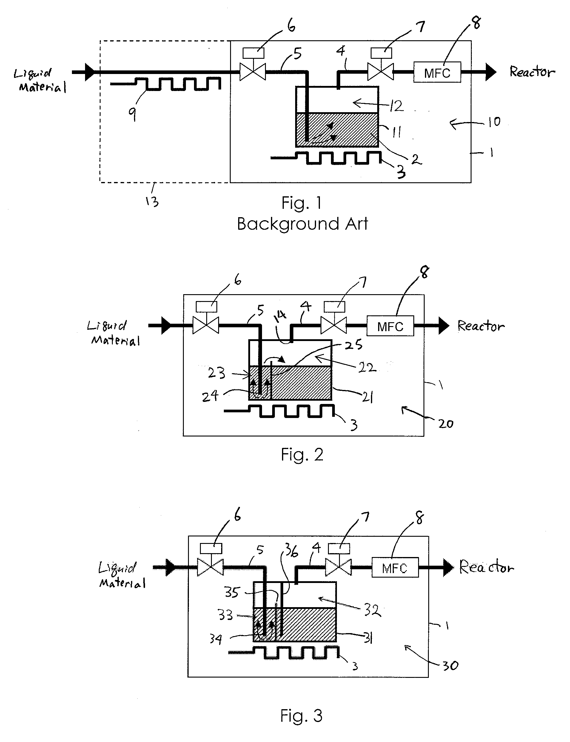
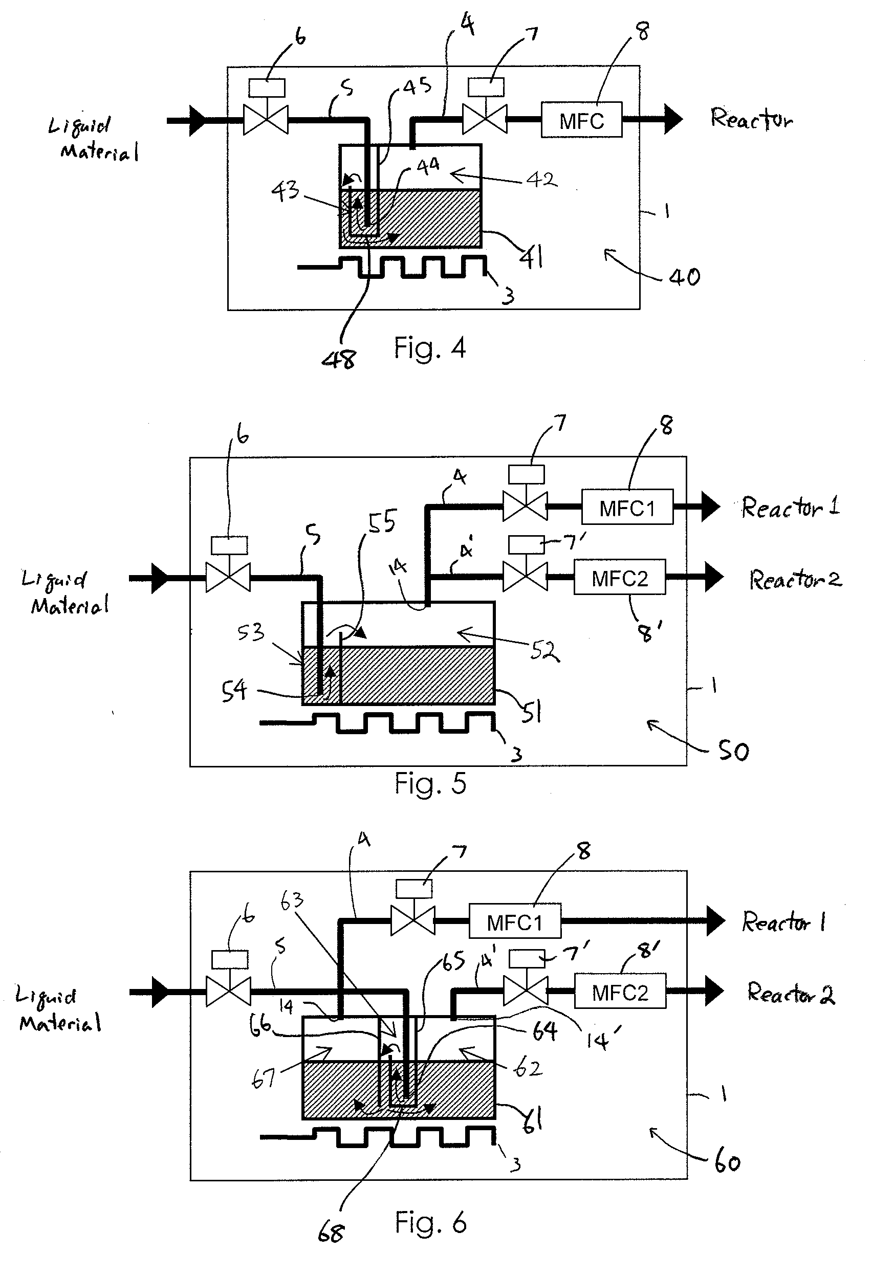
[0010]The above embodiments include, but are not limited to, embodiments shown in the present disclosure. In an embodiment, by dividing the vaporization tank into a vaporization compartment and a charging compartment to which a liquid material at room temperature is charged, a decrease of temperature of the liquid material in the vaporization compartment can effectively be inhibited. In an embodiment, by charging the liquid material in the charging compartment, the liquid material can be gradually heated in the charging compartment without special or additional heating before being sent to the vaporization compartment. In an embodiment, by dividing the vaporization tank into the charging compartment and the vaporization compartment at a bottom of the tank, a liquid material at room temperature newly introduced in the charging compartment stays at a bottom of the charging compartment, and the only liquid material previously charged in the charging compartment which has been heated moves upwards and overflows over an upper portion of the partition wall to the vaporization compartment. In an embodiment, by making the partition wall using a material having a lower thermal conductivity, such as quartz or resin, than that of a material constituting the tank, a decrease of temperature of the liquid material in the vaporization compartment can effectively be inhibited.

Problems solved by technology

If a liquid material which has passed through a room temperature environment is charged into the small vaporization tank, the temperature of the liquid material stored in the vaporization tank suddenly decreases, thereby rendering gas flow unstable.
In the above, if the liquid material is insufficiently heated upstream of the vaporization apparatus 1, the temperature of the liquid material in the tank fluctuates, thereby rendering the flow of vaporized material (gas flow) unstable.
Furthermore, the preheating section including the heater is additional equipment and requires additional control.

Method used


Image

  • Liquid material vaporization apparatus for semiconductor processing apparatus
  • Liquid material vaporization apparatus for semiconductor processing apparatus
  • Liquid material vaporization apparatus for semiconductor processing apparatus

Examples


Embodiment Construction

[0016]The present invention will be explained in detail with reference to preferred embodiments. The preferred embodiments are not intended to limit the present invention. In embodiments, the present invention is characterizable by providing a charging compartment which is formed inside a vaporization tank, as a buffering zone for preventing sudden temperature changes. The liquid material may be first charged into the charging compartment and heated, causing thermal convection current, whereby the liquid material at an upper portion of the charging compartment, which has a higher temperature than that at a lower portion of the charging compartment, moves to a vaporization compartment, while the liquid material having a lower temperature stays at a bottom of the charging compartment and is gradually heated. In the above embodiments, because the only sufficiently heated portion of the liquid material moves to the vaporization compartment, fluctuation of the temperature of the liquid m...


PUM

PropertyMeasurementUnit
Fractionaaaaaaaaaa
Fractionaaaaaaaaaa
Fractionaaaaaaaaaa

Abstract

A liquid material vaporization apparatus for a semiconductor processing apparatus includes: a vaporization tank; an inner partition wall disposed in the tank for dividing the interior of the tank into a charging compartment and a vaporization compartment which are liquid-communicatable with each other over an upper edge of the inner partition wall. A liquid material charged in the charging compartment overflows over the upper edge of the inner partition wall toward the vaporization compartment to store and vaporize the liquid material in the vaporization compartment.

Description

BACKGROUND OF THE INVENTION[0001]1. Field of the Invention[0002]The present invention generally relates to a liquid material vaporization apparatus for a semiconductor processing apparatus, particularly to a liquid material vaporization apparatus comprising a vaporization tank provided upstream of a semiconductor processing apparatus to supply a vaporized material thereto.[0003]2. Description of the Related Art[0004]A liquid material vaporizer is provided with a vaporization tank which has a small capacity so that its footprint can be small. If a liquid material which has passed through a room temperature environment is charged into the small vaporization tank, the temperature of the liquid material stored in the vaporization tank suddenly decreases, thereby rendering gas flow unstable. In order to stabilize gas flow, the capacity of the vaporization tank needs to be larger, or vaporization needs to be held off until the temperature of the liquid material stored in the tank becomes ...

Claims


Application Information

Patent Timeline
IPC IPC(8): C23C16/455B01D1/14
CPCC23C16/54C23C16/4485
Inventor FURUKAWAHARA, KAZUNORIFUKUDA, HIDEAKI
Owner ASM JAPAN
Why Eureka
Eureka Blog
Learn More