
Programmed changes in hybridization conditions to improve probe signal quality

a hybridization condition and program technology, applied in the field of programed changes in hybridization conditions to improve the signal quality of the probe, can solve the problems of increasing the noise and bias of the signals read from the probe, non-specific binding, and no known method of reducing non-specific binding, so as to improve the signal-to-noise performance of the probe

Inactive Publication Date: 2008-07-17
AGILENT TECH INC
View PDF18 Cites 5 Cited by
  • Summary
  • Abstract
  • Description
  • Claims
  • Application Information

AI Technical Summary

Benefits of technology

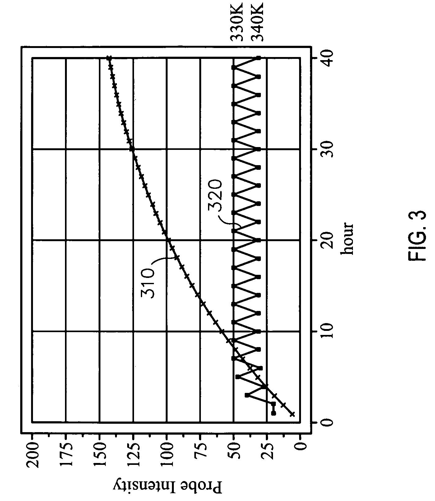
[0007]Methods, systems, computer readable media and kits for improving signal-to-noise performance of a probe include: providing a probe for hybridization with a sample; hybridizing the probe with the sample at a first hybridization stringency over a first hybridization time period; and, following the hybridization over the first hybridization time period, hybridizing the probe with the sample at a second hybridization stringency over a second hybridization time period.
[0008]Methods, systems, kits and computer readable media are provided for improving signal-to-noise performance of probes on an array. A sample is provided, containing sequences that provide perfect complementary matches to sequences contained on at least some of said probes; and the probes are hybridized with the sample, while cycling the stringency of hybridization conditions during the hybridization.

Problems solved by technology

One problem relating to microarray assays is non-specific binding, where probes on the microarray bind to other sequences than the intended target, in addition to binding to the intended target.
This increases both the noise and the bias of the signals read from the probes.
There is currently no known method of reducing non-specific binding during the hybridization process.

Method used


Image

  • Programmed changes in hybridization conditions to improve probe signal quality
  • Programmed changes in hybridization conditions to improve probe signal quality
  • Programmed changes in hybridization conditions to improve probe signal quality

Examples


Embodiment Construction

[0017]Before the present methods, systems and computer readable media are described, it is to be understood that this invention is not limited to particular genes, genomes, methods, method steps, statistical methods, hardware or software described, as such may, of course, vary. It is also to be understood that the terminology used herein is for the purpose of describing particular embodiments only, and is not intended to be limiting, since the scope of the present invention will be limited only by the appended claims.

[0018]Where a range of values is provided, it is understood that each intervening value, to the tenth of the unit of the lower limit unless the context clearly dictates otherwise, between the upper and lower limits of that range is also specifically disclosed. Each smaller range between any stated value or intervening value in a stated range and any other stated or intervening value in that stated range is encompassed within the invention. The upper and lower limits of ...


PUM

PropertyMeasurementUnit
hybridization time periodaaaaaaaaaa
signal-to-noise performanceaaaaaaaaaa

Abstract

A method of improving signal-to-noise performance of a probe. A probe or set of probes is provided for hybridization with a sample. The probe or set of probes is hybridized with the sample at a first hybridization stringency over a first hybridization time period. Following the hybridization over the first hybridization time period, the probe or set of probes is hybridized with the sample at a second hybridization stringency over a second hybridization time period. A method of improving signal-to-noise performance of probes on an array includes providing a sample containing sequences that provide perfect complementary matches to sequences contained on at least some of said probes; and hybridizing the probes with the sample, while cycling the stringency of hybridization conditions during the hybridization.

Description

CROSS-REFERENCE[0001]This application is related to application Ser. No. (application Ser. No. not yet assigned, Attorney's Docket No. 10051736-1) filed concurrently herewith and titled “Array Design Facilitated by Consideration of Hybridization Kinetics”, which is hereby incorporated herein, in its entirety, by reference thereto.BACKGROUND OF THE INVENTION[0002]Arrays of binding agents or probes, such as polypeptide and nucleic acids, have become an increasingly important tool in the biotechnology industry and related fields. These binding agent arrays, in which a plurality of probes are positioned on a solid support surface in the form of an array or pattern, find use in a variety of different fields, e.g., genomics ( in sequencing by hybridization, SNP detection, differential gene expression analysis, CGH analysis, location analysis, identification of novel genes, gene mapping, finger printing, etc.) and proteomics.[0003]In using such arrays, the surface-bound probes are contacte...

Claims


Application Information

Patent Timeline
Patent Type & Authority Applications(United States)
IPC IPC(8): C40B40/00C40B99/00G06F19/00
CPCC12Q1/6876C40B30/04C40B40/06C40B60/12C40B99/00C12Q2527/137C12Q2527/113C12Q2527/107
Inventor MINOR, JAMES M.
Owner AGILENT TECH INC
Learn More