
Reference signal generators

a signal generator and reference signal technology, applied in oscillator generators, generating/distributing signals, pulse techniques, etc., can solve the problems of general failure to meet these more demanding requirements, and achieve the effect of improving the signal-to-noise performan

Active Publication Date: 2007-01-30
MEDIATEK INC
View PDF16 Cites 11 Cited by
  • Summary
  • Abstract
  • Description
  • Claims
  • Application Information

AI Technical Summary

Benefits of technology

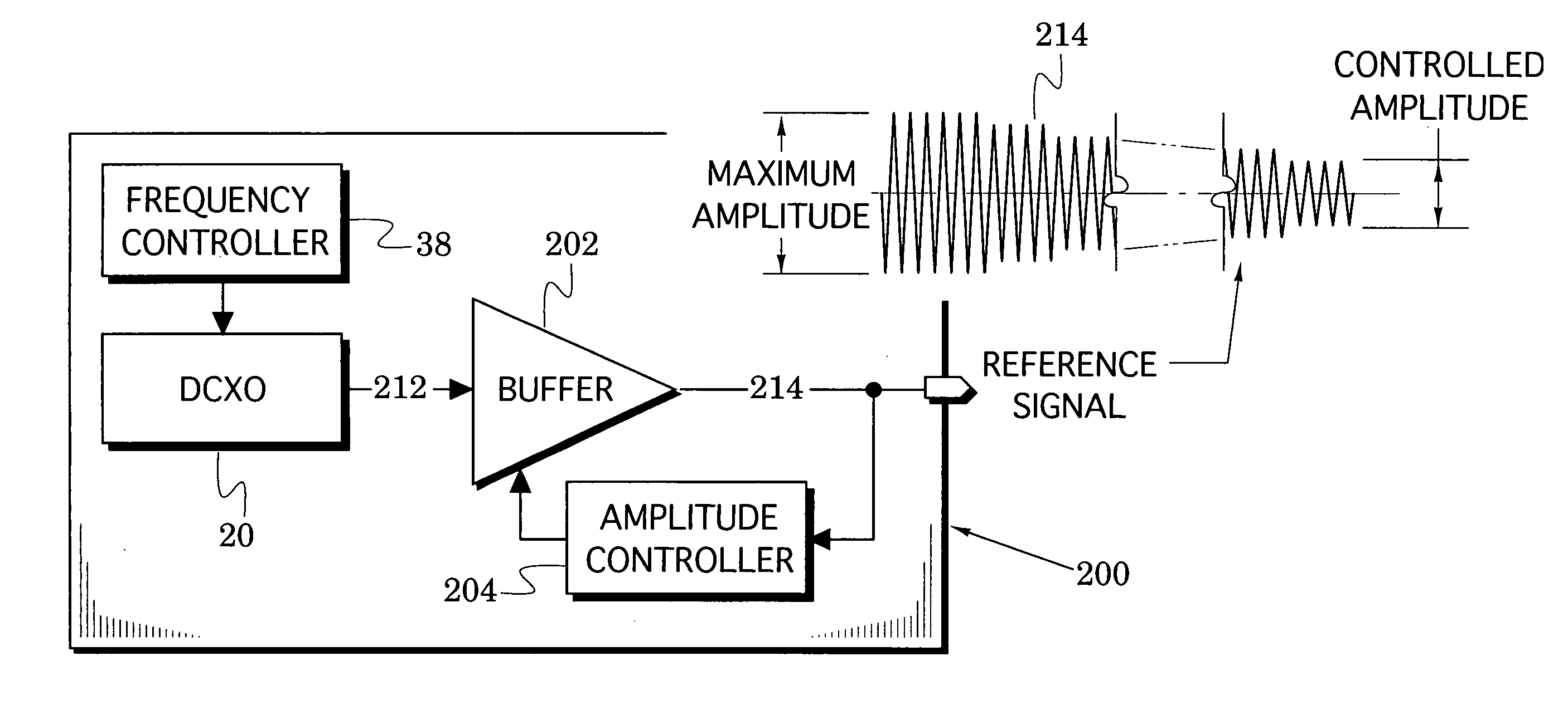
[0006]The present invention is directed to reference oscillator structures that automatically adjust a reference signal's amplitude at system loads of unknown capacitances while independently maintaining an oscillator amplitude that enhances its signal-to-noise performance. Requirements for the reference amplitude, therefore, do not compromise requirements for the amplitude level of the oscillator signal.

Problems solved by technology

Although conventional reference signal generators have met the needs of previous wireless systems, they have generally failed to meet these more demanding requirements.

Method used


Image

  • Reference signal generators
  • Reference signal generators
  • Reference signal generators

Examples


Embodiment Construction

[0018]Reference signal generator embodiments are presented below which are particularly useful in a variety of wireless communication systems (e.g., cellular telephones) because they automatically adjust a reference signal's amplitude when that signal is delivered into system loads having various (and generally unknown) capacitances.

[0019]The amplitude is preferably adjusted downward from an initial maximum to a controlled amplitude that is sufficient for successful operation of the system elements that present the system loads. This downward adjustment insures that their operation is maintained throughout the amplitude leveling process. Spurious signal generation is thus inhibited, current drain is reduced, and the amplitude level of a crystal oscillator in the reference signal generator can be set independently to maximize its signal-to-noise performance.

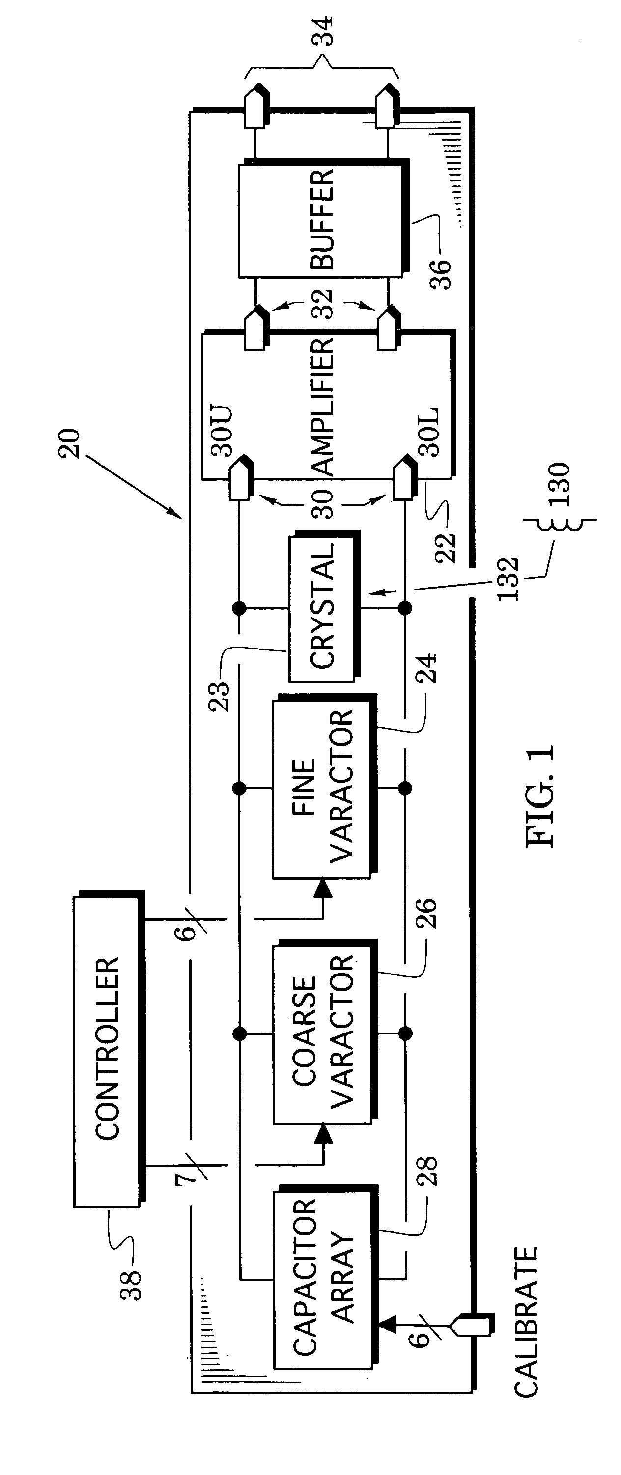
[0020]These reference signal generator embodiments are shown in FIGS. 8–10B and their description is facilitated by preceding it...


PUM


Abstract

Reference signal generators are provided that automatically adjusts a reference signal's amplitude when that signal is delivered into system loads having unknown capacitances. The amplitude is preferably initiated at a maximum amplitude to insure operation of system elements that require the reference signal. It is subsequently adjusted downward to a controlled reference amplitude which is predetermined to be an amplitude sufficient to sustain proper operation of the system elements but sufficiently reduced to minimize the spurious signals typically generated by fast high-level current transitions. In addition, the reduction to the controlled amplitude reduces the system current drain. The level control is realized in a buffer amplifier so that the amplitude level of an oscillator signal can be set independently to maximize its signal-to-noise performance. Accordingly, requirements for the reference amplitude do not compromise requirements for the amplitude level of the oscillator signal.

Description

BACKGROUND OF THE INVENTION[0001]1. Field of the invention[0002]The present invention relates generally to reference signal generators.[0003]2. Description of the Related Art[0004]Modern wireless communication systems are used throughout the world and operate over a variety of frequency bands. For example, the global system for mobiles (GSM) has now been accepted in over 140 countries. This system includes the E-GSM 880–915 and 925–960 MHz transmitting and receiving bands for mobiles, 1710–1785 and 1805–1880 MHz transmitting and receiving bands for digital communications services (DCS), and 1850–1910 and 1930–1990 MHz transmitting and receiving bands for United States Personal Communications Services (PCS).[0005]Components of these wireless systems (e.g., cellular telephones) require reference signal generators that can provide demanding technical performance (e.g., high stability, linear response to a tuning potential, low phase noise and controlled signal levels that enhance syste...

Claims


Application Information

Patent Timeline
Patent Type & Authority Patents(United States)
IPC IPC(8): G06F1/04H03B5/04H03B5/36
CPCH03B5/366H03B5/04
Inventor GOLDFARB, MARC E.BALBONI, EDMUND J.
Owner MEDIATEK INC
Learn More