
Plasmon resonance sensing apparatus and sensing system thereof

a sensing apparatus and plasmon technology, applied in the field of plasmon resonance sensing apparatus and sensing system thereof, can solve the problems of refractive index, light in the sample medium cannot naturally excite surface plasmon resonance, etc., and achieve the effects of improving the signal-to-noise ratio, high sensitivity, and small siz

Active Publication Date: 2012-07-10
NATIONAL CHUNG CHENG UNIV
View PDF7 Cites 12 Cited by
  • Summary
  • Abstract
  • Description
  • Claims
  • Application Information

AI Technical Summary

Benefits of technology

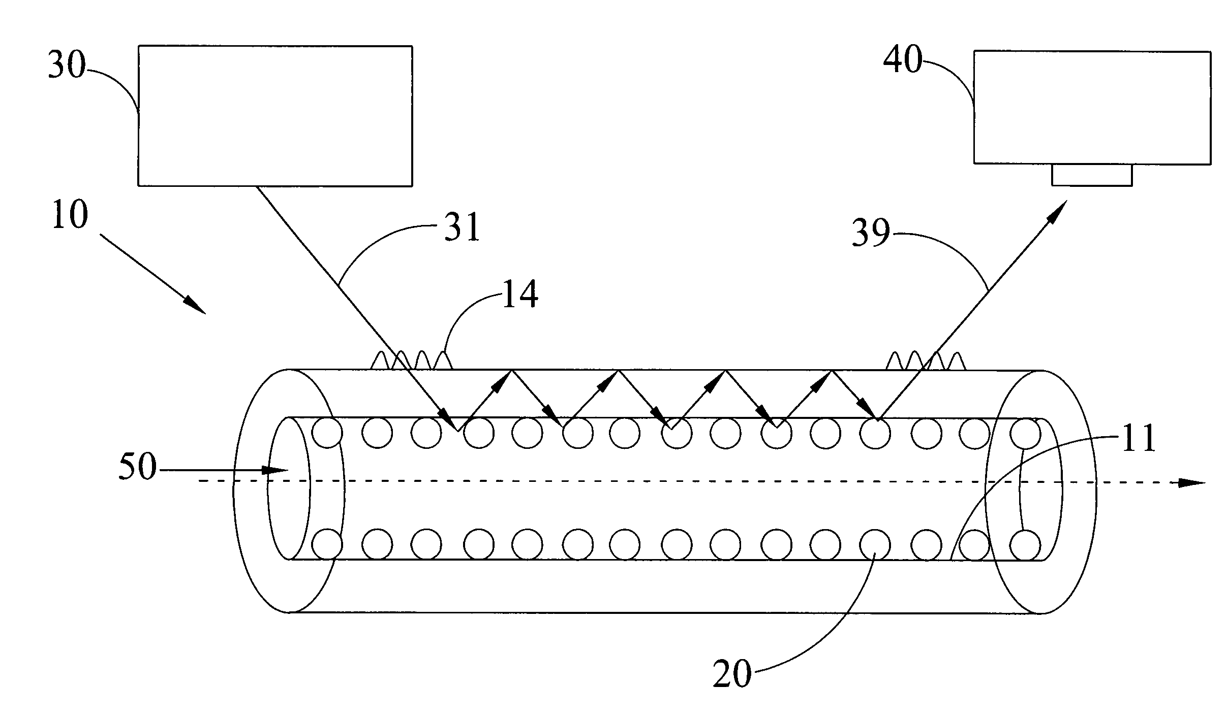
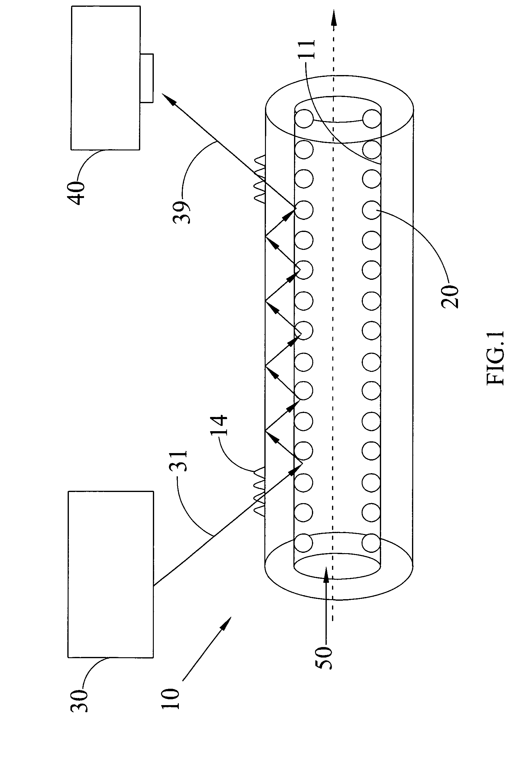
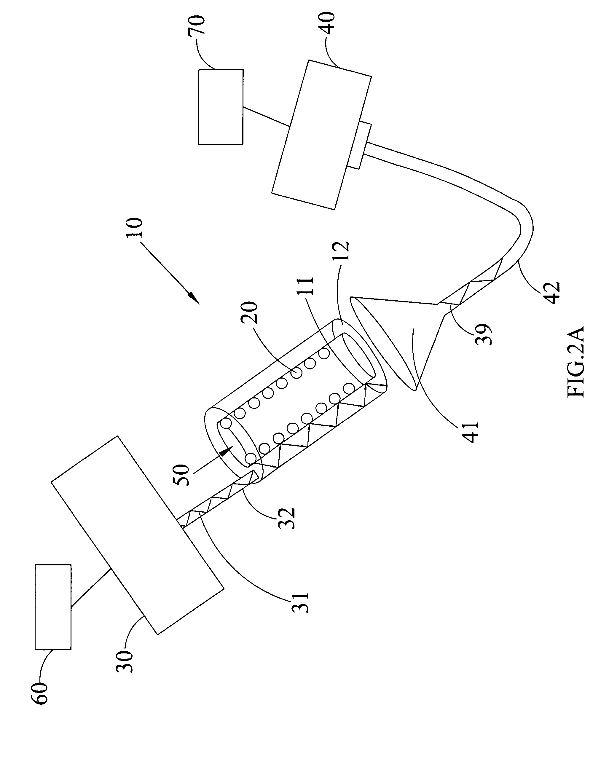
[0010]The present invention uses a multiple of a tubular waveguide with a plurality of total internal reflections to accumulate the signal change of light attenuation by the LPR to improve the performance of the signal-to-noise ratio. Since the tubular waveguide substrate is adopted, the sensing system has the advantages of a small size and a self-contained sample holding design. If the tubular waveguides are arranged in an array, the sensing system may have a high sensitivity as well as a high throughput.

Problems solved by technology

However, light in the sample medium cannot naturally excite surface plasmon resonance and a high refractive index-prism or grating is required.

Method used


Image

  • Plasmon resonance sensing apparatus and sensing system thereof
  • Plasmon resonance sensing apparatus and sensing system thereof
  • Plasmon resonance sensing apparatus and sensing system thereof

Examples


Embodiment Construction

[0028]To make it easier for our examiner to understand the technical characteristics of the present invention, preferred embodiments with accompanying drawings are used for the detailed description of the invention, wherein same elements are represented by same respective numerals.

[0029]Those of ordinary skilled in the art will realize that the following detailed description of the exemplary embodiment(s) is illustrative only and is not intended to be in any way limiting. Other embodiments will readily suggest themselves to such skilled persons having the benefit of this disclosure. Reference will now be made in detail to implementations of the exemplary embodiment(s) as illustrated in the accompanying drawings. The same reference indicators will be used throughout the drawings and the following detailed description to refer to the same or like parts.

[0030]With reference to FIG. 1 for a schematic view of a tubular waveguide plasmon resonance sensing system in accordance with a first...


PUM

PropertyMeasurementUnit
wavelengthaaaaaaaaaa
refractive indexaaaaaaaaaa
shapeaaaaaaaaaa

Abstract

A plasmon resonance sensing system includes a light source, a waveguide component and a photon detector. The light source provides an incident light. The waveguide component has a tubular internal wall and a noble metal nanoparticle layer disposed on the tubular internal wall and contacted with a desired testing matter. The waveguide component is made of a light transmitting material for guiding the incident light to have an interaction with the noble metal nanoparticle layer. The photon detector detects an emergent light exiting the waveguide component after the interaction of the noble metal nanoparticle layer with the desired testing matter. The system further includes a first optical fiber installed between the light source and the waveguide component for transmitting the incident light to the waveguide component, a lens and a second optical fiber. The lens collects and transmits the emergent light to the photon detector through the second optical fiber.

Description

FIELD OF THE INVENTION[0001]The present invention generally relates to a plasmon resonance sensing apparatus and a sensing system thereof, and more particularly to a surface plasmon resonance sensing system using a tubular waveguide component as a container of a desired testing sample.BACKGROUND OF THE INVENTION[0002]In general, surface plasmon resonance refers to a phenomenon having a light at a certain incident angle (the resonance angle) hits a thin metal film so that the light reflected from the film drops to a minimum intensity. However, light in the sample medium cannot naturally excite surface plasmon resonance and a high refractive index-prism or grating is required. When a light beam is incident through the prism on the surface of the thin metal film at total reflection angle, the evanescent wave interacts with the sample, and at the resonance angle, it couples with the surface plasmon. Hence, a fraction of the incident light energy transfers to surface plasmon resonance an...

Claims


Application Information

Patent Timeline
Patent Type & Authority Patents(United States)
IPC IPC(8): G01N21/55
CPCG01N21/554
Inventor CHAU, LAI-KWANCHANG, WEI-ZHECHEN, SHIN-HUEI
Owner NATIONAL CHUNG CHENG UNIV
Learn More