
Light or weathering testing device comprising a specimen enclosure with an integrated UV radiation filter

a testing device and enclosure technology, applied in the direction of instruments, chemical/physical/physicochemical processes, material analysis, etc., can solve the problems of high instability of the assembly as a whole, testing being out of tolerance, etc., and achieve the effect of greater freedom

Inactive Publication Date: 2008-07-17
ATLAS MATERIAL TESTING TECH L L C
View PDF32 Cites 10 Cited by
  • Summary
  • Abstract
  • Description
  • Claims
  • Application Information

AI Technical Summary

Benefits of technology

[0012]Another advantage of the present invention is that the UV radiation filter is no longer exposed to high thermal stress because it is no longer located in the direct vicinity of the xenon radiator. Since some distance away from the xenon radiator, because of the temperature control, no such fluctuations in temperature occur as in the vicinity of the xenon radiator, the transmission characteristic of the UV radiation filter can now be maintained constant, it being particularly when using an edge filter such as a WG320 filter that the edge length can be maintained constant due to the temperature being relatively stable. This now makes it possible, for example, to satisfy the tolerances specified for determining the light protection factor in accordance with pertinent standards, for example DIN 67501 or the COLIPA method. A further advantage of the device in accordance with the invention is that due to the fact that the UV radiation filter is no longer in the direct vicinity of the xenon radiator, there is now greater freedom in designing the UV radiation filter, particularly the thickness of the UV radiation filter.
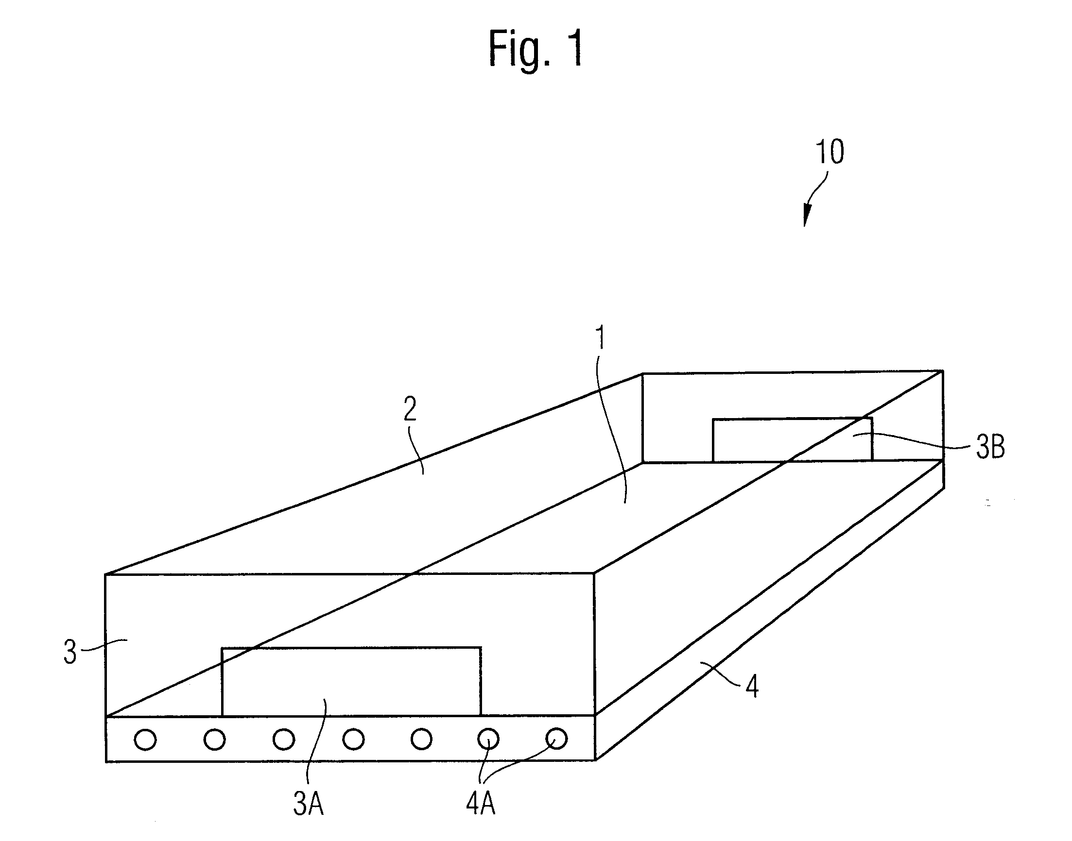
[0013]In one preferred embodiment of the device in accordance with the invention it is provided for that the enclosure comprises a bottom wall for mounting the specimen, an UV radiation filter sited facing the bottom wall and a plurality of sidewalls interconnecting the bottom wall and the UV radiation filter. In this arrangement it may be provided for in particular that the top wall facing the bottom wall of the enclosure is formed entirely by the UV radiation filter. It is, however, just as possible that the UV radiation filter is formed by a window within the top wall.
[0014]The UV radiation filter has preferably the shape of a rectangular disk, the enclosure comprising four sidewalls each of which joins the four side edges of the UV radiation filter to the bottom wall to make it possible to configure the enclosure light-tight so that no stray light whatsoever or substantially no stray light of the xenon radiator attains the specimen. In this arrangement the light-tight seal of the enclosure may be achieved by commercially available seals.
[0015]With weathering apparatuses a distinction is made generally between weathering apparatuses with immobile specimens, such as the SUNTEST apparatus of the applicant, and weathering apparatuses having mobile specimens. With weathering apparatuses having immobile specimens surfaces are provided for mounting the specimens on an inner wall of the weathering chamber which is usually the horizontal bottom plate of the weathering chamber, these specimens mostly being rectangular plates of standard size. Facing the bottom plate, i.e., on a top horizontal inner wall, the UV radiation sources are mounted. With weathering apparatuses having mobile specimens, by contrast, the UV radiation source is arranged as a central rod-shaped radiation source and the specimens are mounted on a frame which can be made to rotate. Here too, the likewise usually plate-type specimens having the surface to be tested are exposed to the radiation source continually during rotation.
[0016]The device in accordance with the invention can be put to use in both types of weathering apparatuses. In a weathering apparatus in which the specimens are immobile the bottom wall of the enclosure is formed by the mounting surface, formed generally by a portion of an inner wall of the weathering chamber, whereas in a weathering apparatus in which the specimens are mobile an enclosure is provided which is movable within the weathering chamber, it in particular being made to orbit the UV radiation source. In this arrangement the enclosure can be secured to a frame capable of being rotated within the weathering chamber, the top wall of the enclosure comprising the UV radiation filter always facing the UV radiation source.
[0017]In weathering apparatuses having immobile specimens, such as the SUNTEST apparatus of the applicant, it is provided for, as a rule, that air is circulated within the weathering chamber such that the air streams over the specimens substantially in a laminar flow in thus ensuring a constant ambient temperature in the direct vicinity of the specimen. This is achievable with a device in accordance with the invention by the two facing sidewalls of the enclosure being formed with ports for passage of a gaseous medium. Preferably, in this case, feeder lines, such as flexible conduits or the like, are directly connected to the ports, so that the ports too, are sealed off to prevent the ingress of stray light into the interior of the enclosure.

Problems solved by technology

The tolerances on the testing requirements for determining the light protection factor by the COLIPA method are so tight that a change in ambient temperature of 40° K can result in the test being out of tolerance.
This means that the WG320 filters need to be between 0.7 to 1 mm thick, resulting in the assembly as a whole being highly unstable with strips 10 mm wide and approximately 300 mm long.

Method used


Image

  • Light or weathering testing device comprising a specimen enclosure with an integrated UV radiation filter
  • Light or weathering testing device comprising a specimen enclosure with an integrated UV radiation filter
  • Light or weathering testing device comprising a specimen enclosure with an integrated UV radiation filter

Examples


Embodiment Construction

[0026]Referring now to FIG. 1 there is illustrated in perspective an enclosure in accordance with the invention for a device for light or weathering testing specimens. The enclosure 10 comprises a bottom wall 1 on which the specimens to be tested can be suitable arranged. For this purpose suitably shaped stages to which the specimens can be secured can be arranged on the bottom wall 1. As is usual for weathering tests, the specimens may be standard size rectangular disks provided with a coating to be tested.

[0027]Sited facing the bottom plate is a UV radiation filter 2 constituting the top plate of the enclosure. As described above this UV radiation filter may be a WG320 filter. In the example aspect as shown, the top of the enclosure 10 is entirely taken up by the UV radiation filter. But it may also be provided for that the UV radiation filter is merely provided as a window in an otherwise light-tight top wall. The enclosure 10 is intended to be sited within a device in accordance...


PUM


Abstract

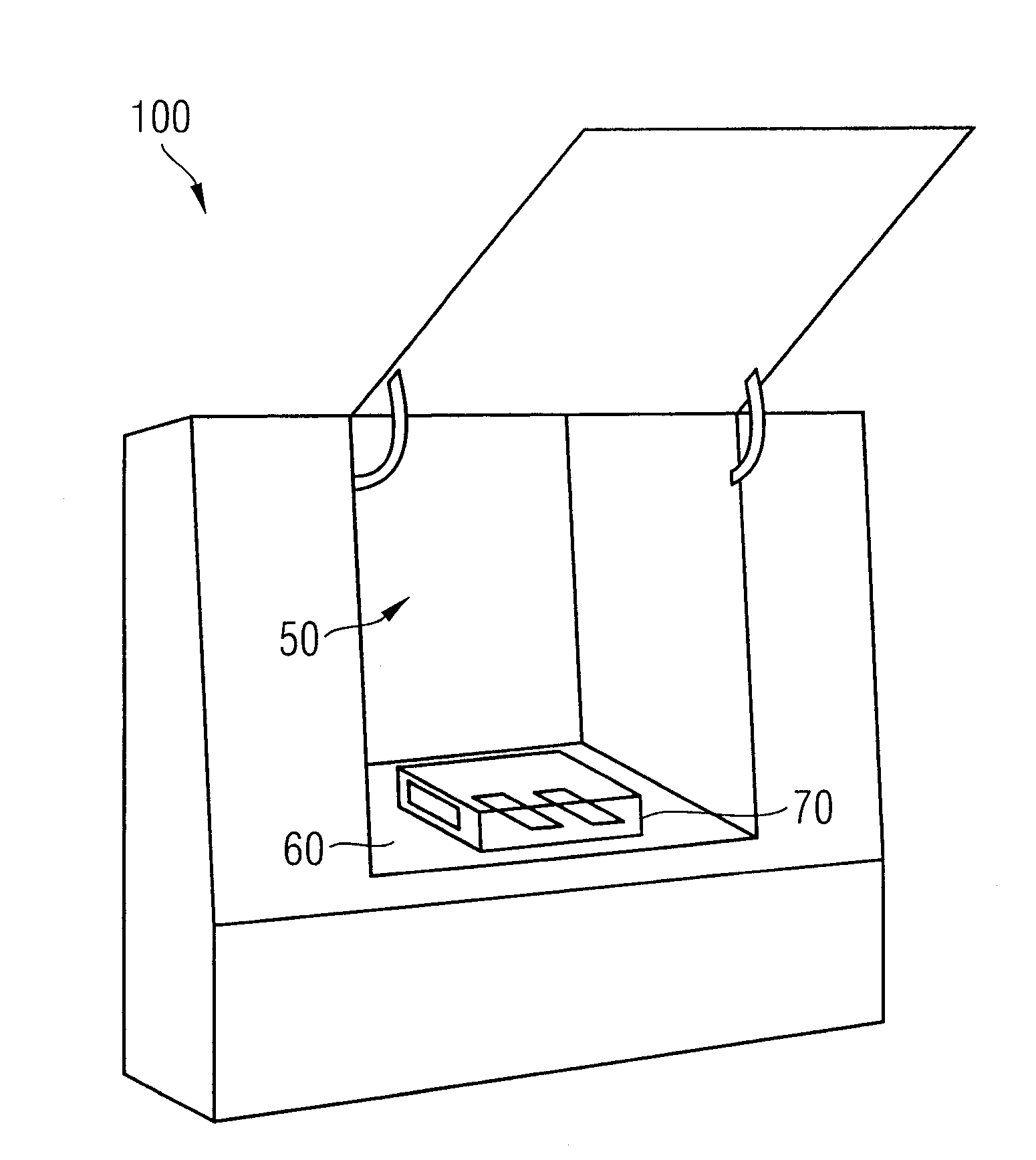
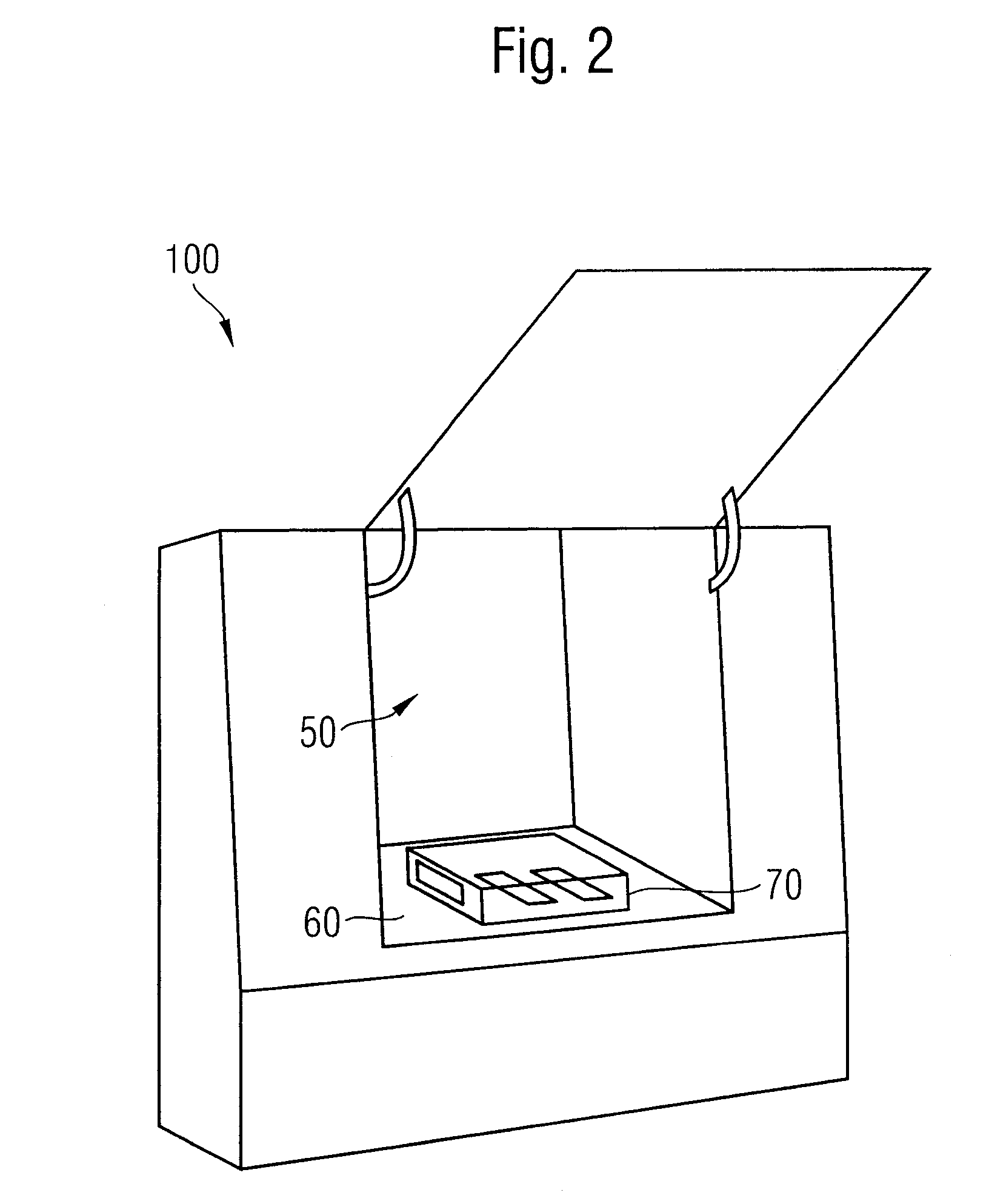
The device comprises a chamber in which a UV radiation source and an enclosure are arranged, the enclosure comprising a bottom wall for mounting a specimen, a UV radiation filter facing the bottom wall and a plurality of sidewalls interconnecting the bottom wall and the UV radiation filter.

Description

FIELD OF THE INVENTION[0001]The present invention relates to a light or weathering testing device and to an enclosure for one such device.BACKGROUND OF THE INVENTION[0002]The object of devices for artificial weathering material specimens is to estimate the useful life of materials which in application are continually exposed to natural weather conditions and thus degrade under climatic influencing factors such as light and heat of the sun, moisture, and the like. To obtain a good simulation of the natural weather conditions the spectral energy distribution of the light generated in the device needs to correspond as best possible to that of natural sunlight, this being the reason why xenon radiators are employed as the source of radiation in such devices. Accelerated aging testing materials is achieved by irradiating the specimens constantly and with added intensity to speed up aging of the specimens.[0003]The majority of the material specimens tested in artificial weathering devices...

Claims


Application Information

Patent Timeline
IPC IPC(8): G01N21/00
CPCG01N17/002B01J19/123G01N17/004
Inventor SCHOENLEIN, ARTUR
Owner ATLAS MATERIAL TESTING TECH L L C
Learn More