
Stackable semiconductor package and the method for making the same

a technology of semiconductor packaging and stacking pads, which is applied in the direction of semiconductor devices, semiconductor/solid-state device details, electrical apparatus, etc., can solve the problems of cracking of second substrates b>13/b>, and achieve the effect of preventing the contamination of the first bonding pad

Inactive Publication Date: 2008-07-10
ADVANCED SEMICON ENG INC
View PDF6 Cites 102 Cited by
  • Summary
  • Abstract
  • Description
  • Claims
  • Application Information

AI Technical Summary

Benefits of technology

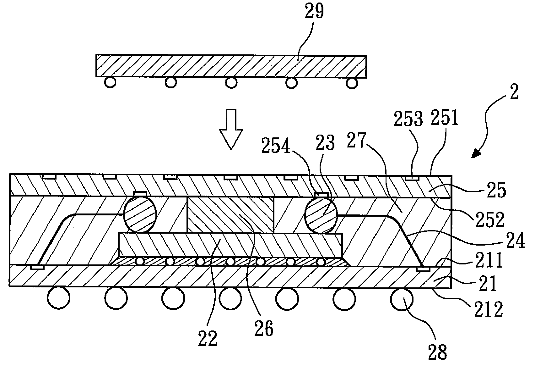
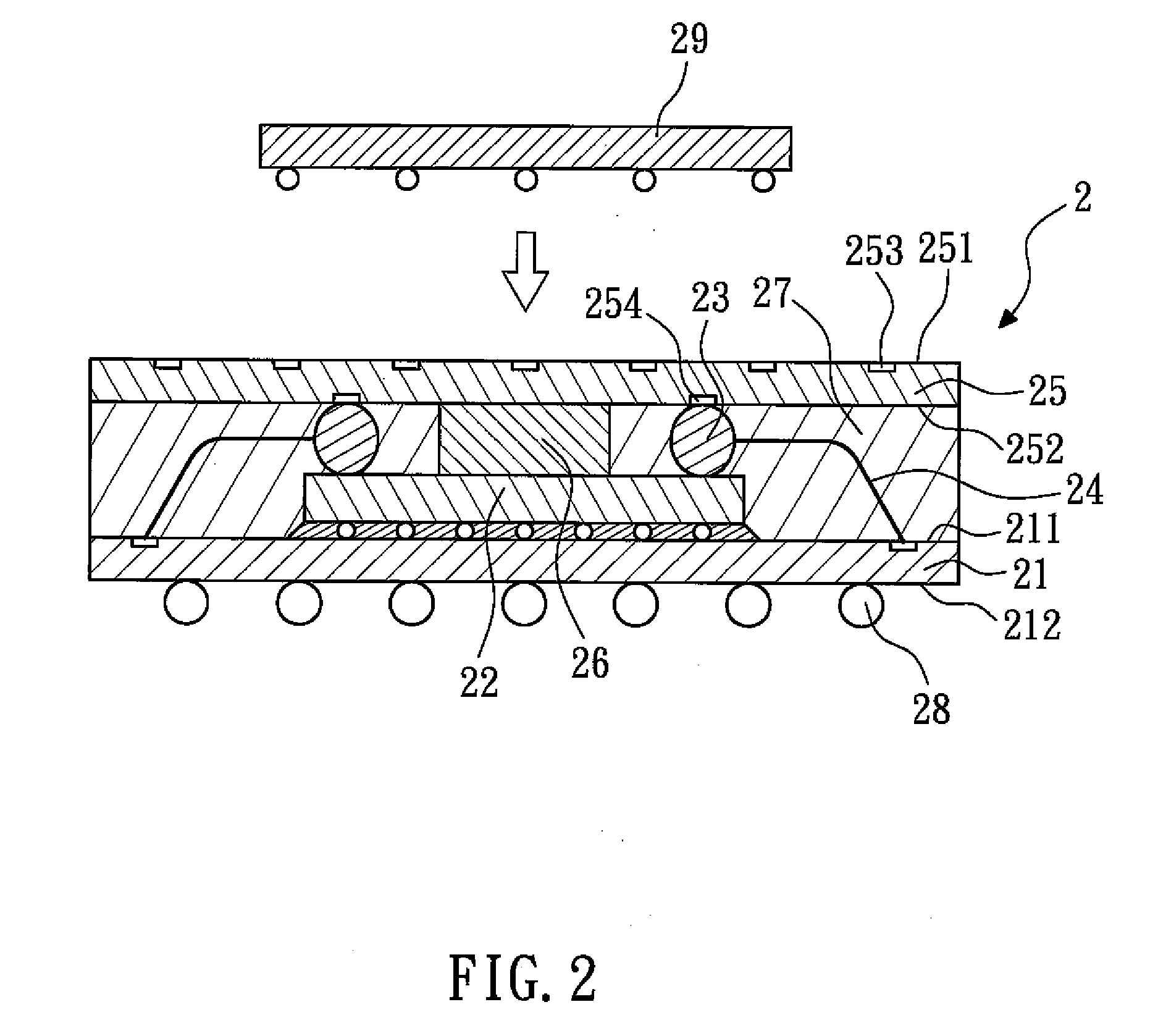
[0009]In the present invention, the second substrate will not undergo wire bonding, and thus will not be suspended and shake or sway as in a conventional package. Further, during the molding process of the molding compound, the molding compound will not overflow between the upper mold and the first surface of the second substrate, thus preventing the first bonding pads from being contaminated. Also, the upper surface of the stackable semiconductor package (i.e., the first surface of the second substrate) is an extremely flat surface, and more packages or other devices, or larger ones, can be disposed thereon.

Problems solved by technology

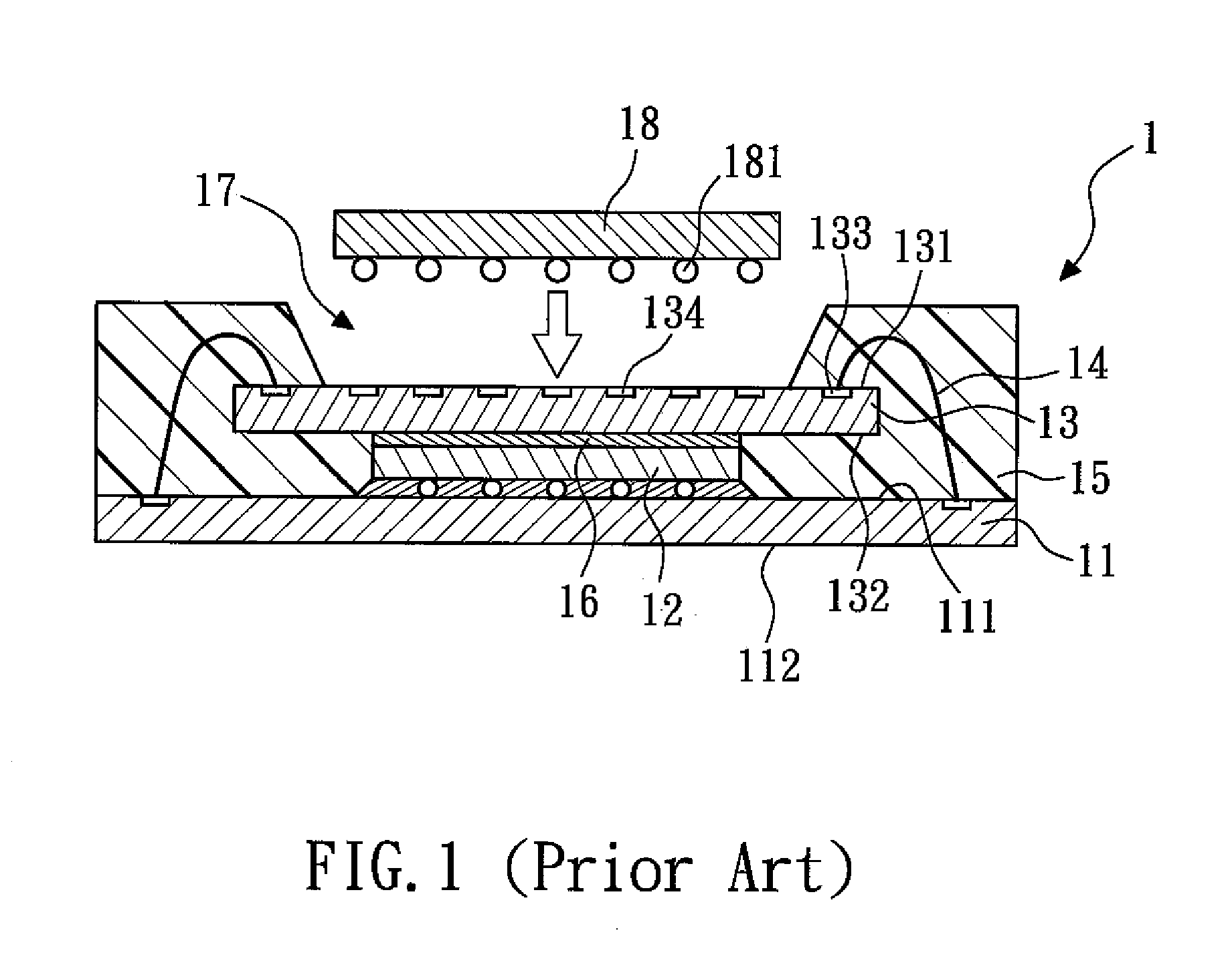
Further, during the wire bonding process, under an extremely high downward pressure, the second substrate 13 might crack.

Method used


Image

  • Stackable semiconductor package and the method for making the same
  • Stackable semiconductor package and the method for making the same
  • Stackable semiconductor package and the method for making the same

Examples


first embodiment

[0024]FIG. 2 shows a schematic cross-sectional view of a stackable semiconductor package according to the present invention. The stackable semiconductor package 2 comprises a first substrate 21, a semiconductor device 22, a plurality of stud bumps 23, a plurality of first wires 24, a second substrate 25, a support compound 26, a molding compound 27, and a plurality of solder balls 28.

[0025]The first substrate 21 has a first surface 211 and a second surface 212. The semiconductor device 22 is disposed on the first surface 211 of the first substrate 21, and electrically connected to the first surface 211 of the first substrate 21. In this embodiment, the semiconductor device 22 is a chip, and is attached to the first surface 211 of the first substrate 21 by flip-chip bonding.

[0026]The stud bumps 23 (for example, gold stud bumps) are disposed above the semiconductor device 22. In this embodiment, the stud bumps 23 are disposed on a top surface of the semiconductor device 22. The first ...

second embodiment

[0035]FIG. 4 shows a schematic cross-sectional view of a stackable semiconductor package according to the present invention. The stackable semiconductor package 3 comprises a first substrate 31, a semiconductor device 32, a plurality of second wires 33, an intermediate device 34, a plurality of stud bumps 35, a plurality of first wires 36, a second substrate 37, a support compound 38, a molding compound 39, and a plurality of solder balls 40.

[0036]The first substrate 31 has a first surface 311 and a second surface 312. The semiconductor device 32 is disposed on the first surface 311 of the first substrate 31, and electrically connected to the first surface 311 of the first substrate 31. In this embodiment, the semiconductor device 32 is a first chip. The semiconductor device 32 is adhered to the first surface 311 of the first substrate 31, and is electrically connected to the first surface 311 of the first substrate 31 through the second wires 33.

[0037]The intermediate device 34 is ...


PUM


Abstract

The present invention relates to a stackable semiconductor package and the method for making the same. The stackable semiconductor package comprises a first substrate, a semiconductor device, a plurality of stud bumps, a plurality of first wires, a second substrate, and a molding compound. The semiconductor device is disposed on the first substrate and electrically connected to the first substrate. The stud bumps are above the semiconductor device. The first wires are used for electrically connecting the stud bumps and the first substrate. The stud bumps are in contact with the second substrate. The molding compound encapsulates the first substrate, the semiconductor device, the stud bumps, the first wires, and the second substrate, and thus, the second substrate will not undergo wire bonding, and will not be suspended and shake or sway, as present in a conventional stackable semiconductor package.

Description

BACKGROUND OF THE INVENTION[0001]1. Field of the Invention[0002]The present invention relates to a stackable semiconductor package, and more particularly to a stackable semiconductor package using stud bumps to support a substrate.[0003]2. Description of the Related Art[0004]FIG. 1 shows a schematic cross-sectional view of a conventional stackable semiconductor package. The conventional stackable semiconductor package 1 comprises a first substrate 11, a chip 12, a second substrate 13, a plurality of wires 14 and a molding compound 15. The first substrate 11 has a first surface 111 and a second surface 112. The chip 12 is attached to the first surface 111 of the first substrate 11 by flip-chip bonding. The second substrate 13 is adhered to the chip 12 through an adhesive layer 16. The second substrate 13 has a first surface 131 and a second surface 132, and the first surface 131 has a plurality of first bonding pads 133 and a plurality of second bonding pads 134. Viewed from the top,...

Claims


Application Information

Patent Timeline
IPC IPC(8): H01L23/12H01L21/60
CPCH01L24/73H01L2225/1058H01L25/105H01L2224/16H01L2224/2518H01L2224/48091H01L2224/48095H01L2224/48227H01L2225/0651H01L2225/06527H01L2225/06575H01L2924/01079H01L2924/15311H01L2924/1815H01L25/0657H01L2225/1041H01L2225/1023H01L2924/01006H01L2924/01005H01L2924/00014H01L2924/181H01L2924/00011H01L2924/00012H01L2224/0401
Inventor WU, YEN-YICHANG CHIEN, PAO-HUEISUNG, WEI-YUEH
Owner ADVANCED SEMICON ENG INC
Learn More