Eureka AIR delivers breakthrough ideas for toughest innovation challenges, trusted by R&D personnel around the world.

Irreversible humidity exposure dose indicator device

a humidity exposure and indicator device technology, applied in the field of humidity dosimetry, can solve the problems of lint damage to sensitive products, etc., and achieve the effects of high design flexibility, simple use, reading and understanding

Inactive Publication Date: 2008-07-10
APPEALING PRODS
View PDF34 Cites 24 Cited by
  • Summary
  • Abstract
  • Description
  • Claims
  • Application Information

AI Technical Summary

Benefits of technology

[0018]The present invention relates to a new class of structures of HDI that (i) provide a quantitative indication of the exposure dose, (ii) are highly flexible in terms of design so they can be used in different applications that require measuring different ranges of humidity doses, (iii) are of a low-cost character, (iv) do not require a power source and (v) yield results that are very simple to use, read and understand.
[0019]In addition, the devices of this invention completely enclose all the chemicals and materials they use, so that no corrosive materials, e.g., a liquid solution of a fiber, particle or deliquescent salt, can leak from the device. For example, materials like blotter paper or silica particles do not involve leakage potential, such as is present in many disposable humidity measuring devices. The product stored in a package with the HDI will not be contaminated by the detector or its component materials. Materials such as paper sometimes shed fibers and lint. Silica involves the presence of tiny particles. Such particles, fibers and lint may damage products that are sensitive to dust, such as electronic components. Accordingly, the HDI of the present invention resolves the problems that exist with conventional HDI devices.
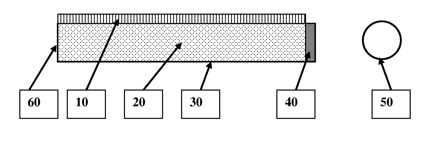
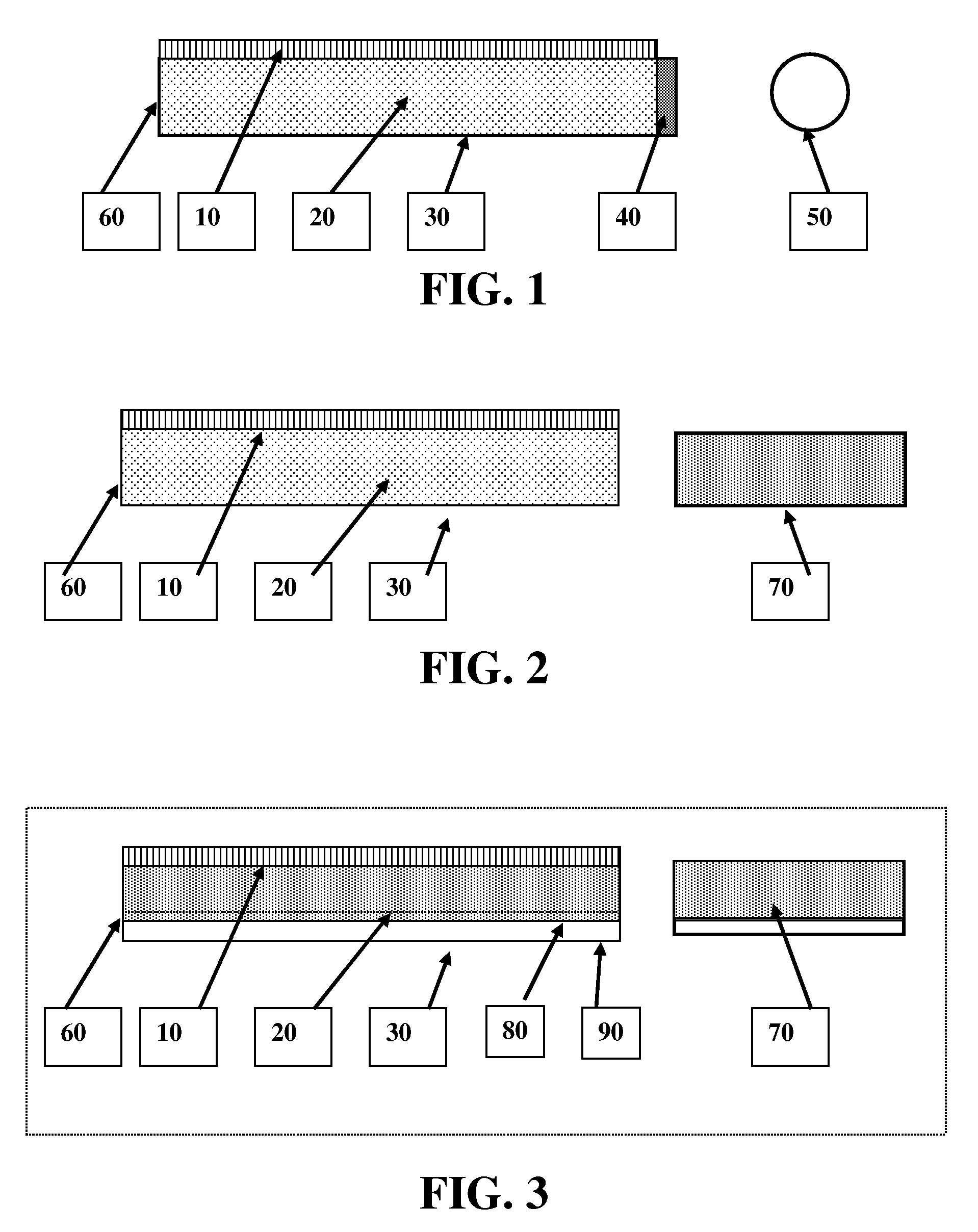
[0021]The detector device of the present invention is based on the principle that the dosimetry of water vapor is determinable by the flux of its diffusion through an opening into a passage that contains, or is in equilibrium with another passage, chamber or other structure that contains, chromogenic material. Water vapor is absorbed very rapidly onto the surface of solid particles as it diffuses and forms a nano-thin aqueous layer that partially dissolves some of the solid or of a coating on the solid surface. When a second solid coated with a chromogen is in intimate contact with the first solid, a chromogenic reaction takes place, which produces a visible color change. The length of the resulting color stain that is formed provides an indication of the integrated exposure dose. The chromophoric reaction may produce a fluorescent or phosphorescent product that can be measured electronically to produce a humidity exposure dose indication.

Problems solved by technology

Such particles, fibers and lint may damage products that are sensitive to dust, such as electronic components.

Method used


Image

  • Irreversible humidity exposure dose indicator device
  • Irreversible humidity exposure dose indicator device
  • Irreversible humidity exposure dose indicator device

Examples


example 1

A Capillary Humidity Dosimeter

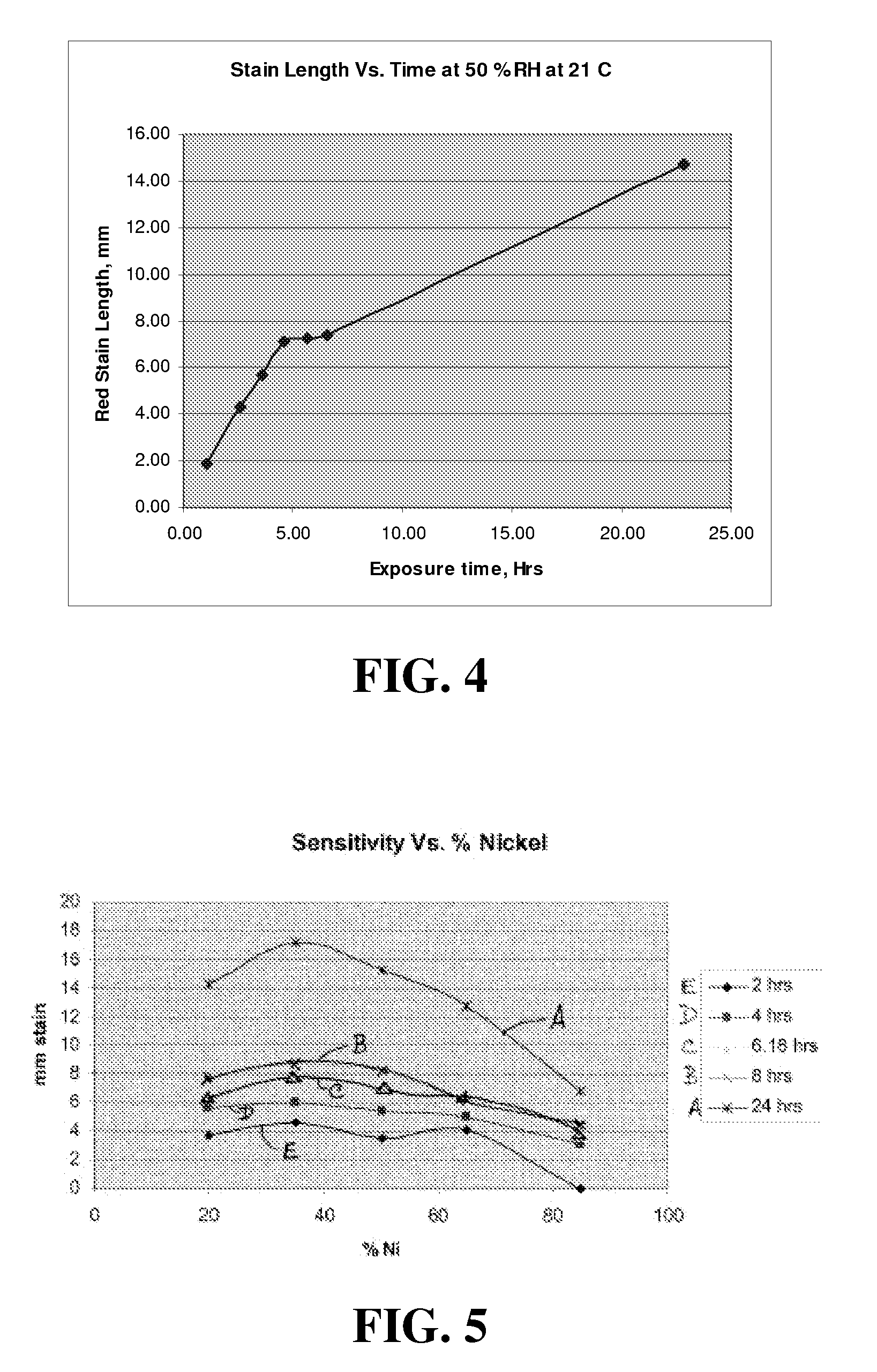
[0069]An HDI was prepared using a glass capillary 90 mm long and having an 1.8 mm OD, and a 1 mm ID, by filling it with a 50×50% wt of 63-200 microns silica gel having a BET surface area of about 300 m2 / gm, coated by dimethyl glyoxime at 33 mg / gm; and nickel hydroxy-oxide powder of comparable particle size dried 2 hours at 150° C. A 1 mm long plug of glass wool was used to close the capillary open end. These dosimeters were exposed to static air with fixed relative humidity of 50% at 21° C., and the length of the red stain formed as a result of the exposure to the humidity was measured, in millimeters, as a function of time, in hours, yielding the curve shown in the graph of FIG. 4.

examples 2-6

A Capillary Humidity Dosimeter With Variable Ratios of Nickel to Silica

[0070]Dosimeters were prepared as described in Example No. 1 but the amount of nickel hydroxy-oxide was varied in the range of 10% to 90%. The results are shown in FIG. 5, which is a graph of length of the color stain, in millimeters, as a function of percent nickel in the chromophoric medium, at various exposure times (2 hrs, 4 hrs, 6.18 hrs, 8 hrs and 24 hrs).

[0071]The data in FIG. 5 show that the greatest sensitivity is obtained when the nickel hydroxy oxide concentration is about 35%.

examples 7-14

The Performance of the Capillary Humidity Dosimeter at Different Fixed RH Values at 21° C.

[0072]The length of the stain formed in the HDI of Example 1 was tested at fixed water vapor pressures. The data are shown in FIG. 6, which is a graph of the logarithm of stain length, in millimeters, as a function of the logarithm of exposure time, in hours, at 21° C., for water vapor pressure of 5.20 mm, 8.68 mm, 13.04 mm, 14.49 mm, 16.61 mm, 17.4 mm, 18.07 mm, and 18.65 mm.


PUM


Abstract

An irreversible humidity exposure dose indicator device, including a housing sealed at a first end thereof and adapted at a second end thereof to admit ambient gas ingress into an interior volume containing chromogenic material. The chromogenic material in contact with water irreversibly absorbs such water to produce a change whose extent is correlative of cumulative exposure of the device to humidity. The device may be configured as an indicator card including an intermediate permeable membrane coated on a first side thereof with a layer of a deliquescent solid and being in contact on a second side thereof with a layer containing a reactive indicator, with a water-permeable layer adjacent to the layer containing the deliquescent coating, enclosed within a water-impermeable transparent enclosure. The device can include an opening to the permeable layer that is shielded by a removable member that is removed to initiate the dosimetric process, and permit water vapor to diffuse through the opening and liquefy the deliquescent material, so that the liquid permeates through the membrane and a visible indication of the location of the wet front is seen as the water contacts the chromogenic material. A scale can be printed on the exterior of the enclosure to permit a viewer to see the progress of the indication, e, g. of a color front.

Description

FIELD OF THE INVENTION[0001]The present invention generally relates to humidity dosimetry, and more specifically to an irreversible humidity exposure dose indicator card for ready determination of the humidity exposure history of a monitored article or environment. A new class of irreversible humidity indicator cards is described herein, which are quantitative and which do not contain a dye. The cards measure quantitatively the integrated exposure dose to humidity and not only the current or contemporary relative humidity. The color-based indication of the cumulative humidity exposure enables an easy observation of the progress of a front of color change.BACKGROUND OF THE INVENTION[0002]When shipping or storing many types of materials, particularly electronic components, it is desirable to know whether those components have been exposed to a particular dose or amount of humidity, since exposure to excessive humidity can cause damage to those components. For example, electronic compo...

Claims


Application Information

Patent Timeline
IPC IPC(8): G01W1/11G01N31/22
CPCG01N21/81Y10T436/202499Y10T436/173845G01N31/222
Inventor ATTAR, AMIR J.STARK, DAN EDWARD
Owner APPEALING PRODS
Why Eureka
Eureka Blog
Learn More