
Solar-powered, liquid-hydrocarbon-fuel synthesizer

Inactive Publication Date: 2008-07-10
JOHNSON ROBERT PAUL
View PDF13 Cites 15 Cited by
  • Summary
  • Abstract
  • Description
  • Claims
  • Application Information

AI Technical Summary

Benefits of technology

[0011]The first objective of this invention is to produce liquid hydrocarbon fuel using abundant raw materials and solar energy. An alternate means of producing liquid hydrocarbon fuel might stabilize the cost of mined oil refined for the production of gasoline, and will ultimately reduce dependence on mined oil. Additional oil-refinery capacity becomes unnecessary. Capital for the addition or replacement of unneeded oil-refinery capacity can be directed toward solar-powered, liquid-hydrocarbon-fuel synthesizers.
[0045]Ancillary power derived from the generator is assumed to consume 247 kilowatts, or 100% of all other work output excluding energy used to focus the heliostat array. Uses might include pumps that transfer water and fuel, pumps that lubricate bearings, and an electric motor that raises carbon from a holding pit to the inlet auger screw. A vacuum pump removes air from the carbon holding pit, which prevents air from entering the synthesizer. An airtight blanket might cover the carbon. Propane gas might fill voids in the carbon as air is removed. Air would likely be purged each time the carbon holding pit is filled. A volume of about 1,900 cubic meters of carbon supplies one solar-powered synthesizer for one year. A cubic bin, 12.4 meters or 41 feet per side, contains enough carbon for a full year of operation, so purging need not be a frequent occurrence. Gravity pulls fuel from the synthesizer catch basin to a settling reservoir where most entrained carbon is removed. A dredge recovers carbon that has settled in the reservoir. A vacuum pump maintains pressure below atmospheric pressure in the fuel catch basin of the synthesizer, which prevents fuel vapors from entering the atmosphere. Surveillance cameras and motion detectors might allow remote monitoring of the synthesizer operation.

Problems solved by technology

Additional oil-refinery capacity becomes unnecessary.
As solar-powered, liquid-hydrocarbon-fuel synthesizers replace oil refinery capacity, pollution-per-transportation-mile declines from lower oil refinery emissions.

Method used


Image

  • Solar-powered, liquid-hydrocarbon-fuel synthesizer
  • Solar-powered, liquid-hydrocarbon-fuel synthesizer
  • Solar-powered, liquid-hydrocarbon-fuel synthesizer

Examples


Embodiment Construction

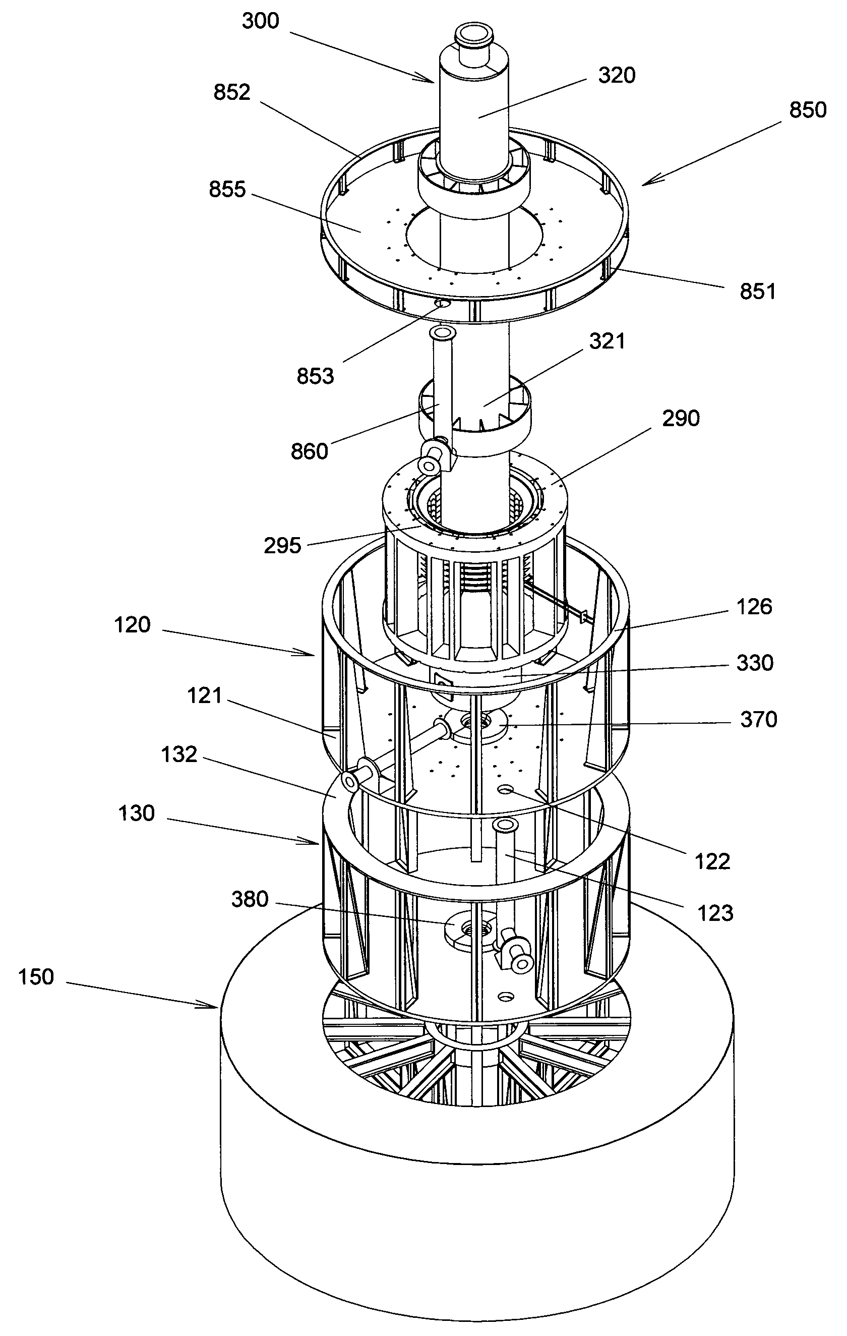
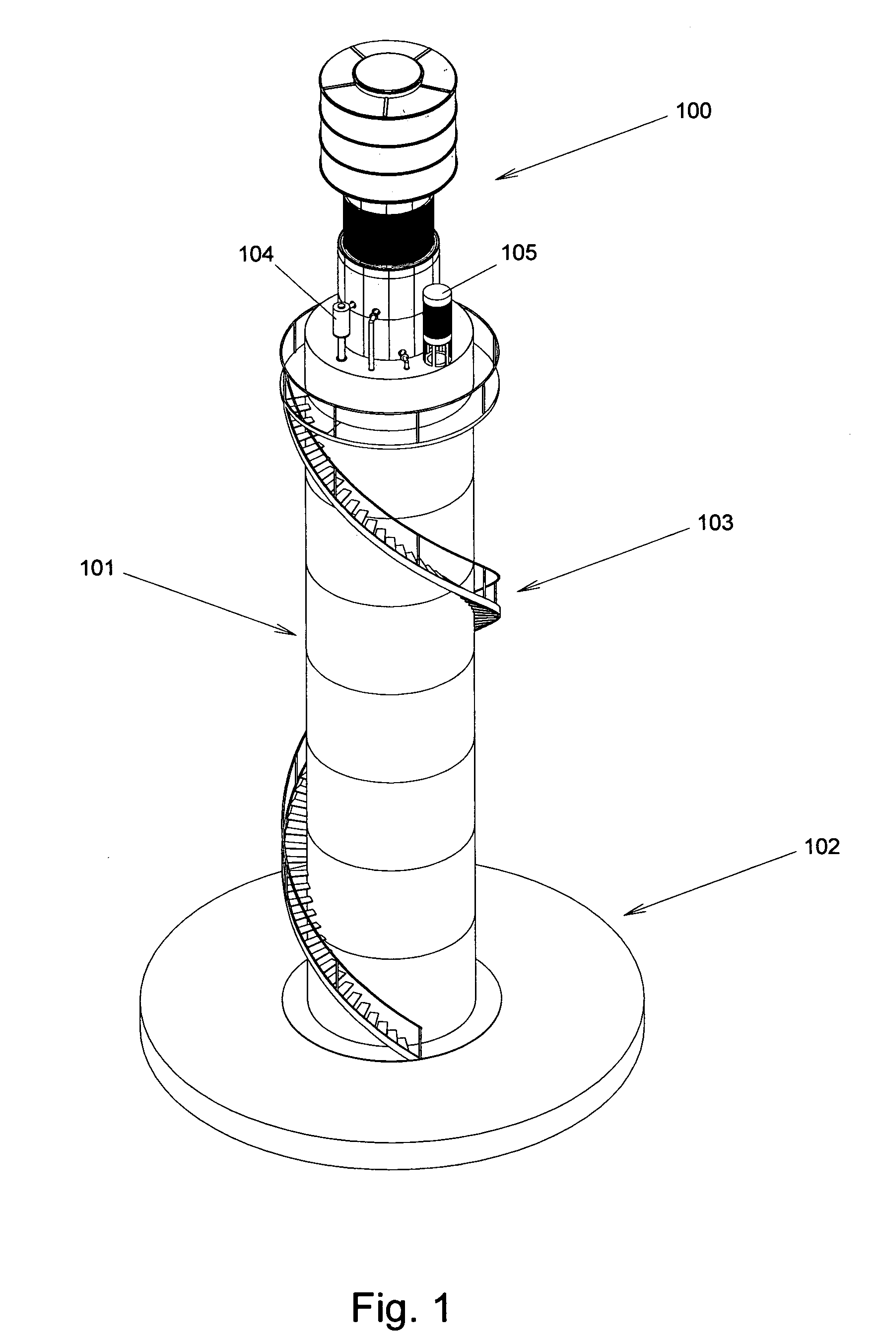
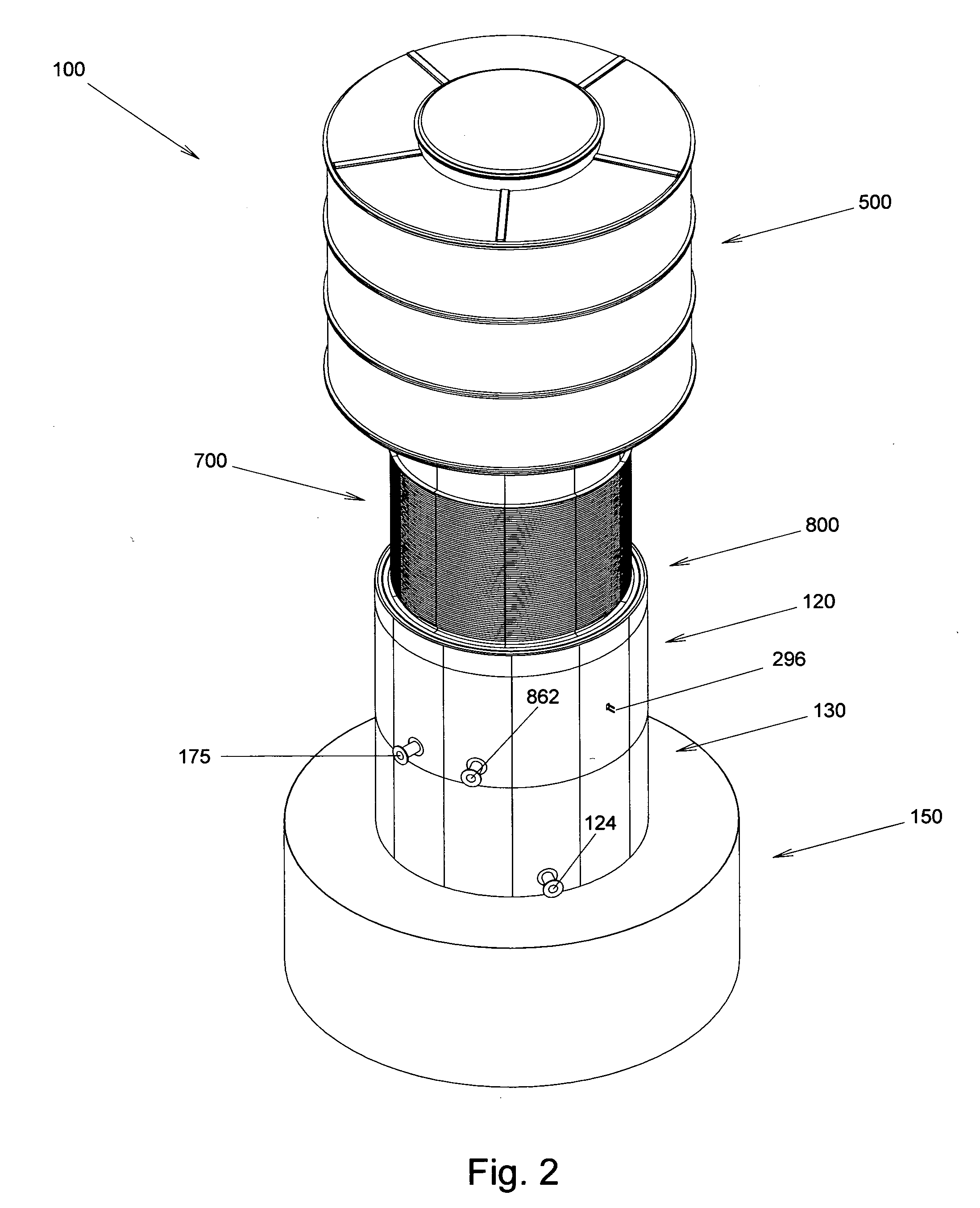
[0076]FIG. 1 is an idealized representation of the liquid-hydrocarbon-fuel synthesizer, 100, sitting atop a tower, 101. The tower height depends upon the production rate of the synthesizer. A smaller output will require a smaller heliostat array, and a shorter tower. FIG. 1 illustrates how a tower might look if built upon a foundation, 102, that doubles as a carbon holding pit. A transfer case, 104, changes the direction of carbon, lifted from the holding pit, from vertical to horizontal. Water might be stored in a tank disposed within the base of said tower. Pump, 105, condenses coolant that lowers the turbine outlet temperature and pressure. Maintenance access to said synthesizer is by stairs, 103. Said tower might include a retractable maintenance crane, not drawn, disposed near the top said tower. The crane lifts the rotating assembly for maintenance. Materials and supplies too heavy to transport by stair could be raised from ground level by such a crane. During operation of sai...


PUM


Abstract

A synchronous reaction cell, rotating as a unit, disassociates hydrogen from water, traps and filters hydrogen, mixes and pressurizes hydrogen and ingested carbon, hydrogenates carbon by surface catalysis, isolates and exhausts liquid hydrocarbon products above a desired density, recirculates gaseous products for further reaction, and expands steam through a turbine to produce rotation and turn an electrical generator. Solar energy focused by heliostats is one means of supplying process heat. Burning natural gas or another fossil fuel in oxygen freed by the disassociation of water provides alternative sources of heat. The reaction cell has a vertical axis-of-rotation making it conducive to mounting on a tower disposed at the center of an array of heliostats. The rotating reaction cell has a large, cylindrical heat-absorbing surface. Electrical output might be used to aim heliostats. Excess electrical generation might be added to the local electrical grid and sold for its value.

Description

CROSS-REFERENCE TO RELATED APPLICATIONS[0001]This application claims priority of provisional patent application Ser. No. 60 / 879,096, filed Jan. 8, 2007, and benefits of a related provisional patent application, Ser. No. 60 / 963,500, filed Aug. 6, 2007.FEDERALLY SPONSORED RESEARCH[0002]Not ApplicableSEQUENCE LISTING[0003]Not ApplicableBACKGROUND OF THE INVENTION[0004]1. Field of Invention[0005]This invention is a reaction cell for synthesizing hydrocarbons. Hydrogen gas wrung from water and carbon catalytically react in a cyclic flow in which liquid products are isolated from gaseous products. The reaction cell uses solar energy as one source of process heat.[0006]2. Description of Prior Art[0007]Hydrocarbons of various forms are used throughout the world to produce heat and work. Most hydrocarbon-fueled processes use atmospheric oxygen and exhaust reaction products into the air. Liquid hydrocarbon fuel is used extensively in transportation. Work is produced in the form of turning tor...

Claims


Application Information

Patent Timeline
IPC IPC(8): F01D1/00H02K7/18F03G6/00B01J8/00F01D15/10B67D99/00
CPCB01J15/005Y02E10/46B01J19/1806B01J2219/0869B01J2219/0871B01J2219/0886B01J2219/0892C10G1/00C10G1/06C10G1/086F01D15/10F03G6/065G06Q50/06H02K7/1823B01J19/127Y02P20/133
Inventor JOHNSON, ROBERT PAUL
Owner JOHNSON ROBERT PAUL
Learn More