Partitioned chimney cap and fireplace venting system

a chimney cap and venting system technology, applied in the field of partitioned chimney caps, can solve the problems of significant heat loss from the room, inefficient heat source of the conventional fireplace, and inability to draw cold air, so as to improve operational efficiency, reduce noise level, and reduce noise level

Inactive Publication Date: 2008-07-03
EBERHARDT H ALFRED
View PDF32 Cites 7 Cited by
  • Summary
  • Abstract
  • Description
  • Claims
  • Application Information

AI Technical Summary

Benefits of technology

[0011]An advantage of the present invention is a fan / motor arrangement for drawing air through the chimney flue to the combustion chamber of a fireplace system and for drawing combustion gases from the combustion chamber through the chimney flue, which arrangement operating at a substantially reduced noise level as measured adjacent to the combustion chamber.
[0012]A further advantage of the present invention is a fireplace chimney cap that provides a pivot effect which improves operational efficiency associated with movement of combustion air and combustion gases through the fireplace system.
[0013]A still further advantage of the present invention is a blower fan / motor arrangement for drawing combustion gases from the combustion chamber through the chimney flue of a fireplace system, which system will operate at a substantially reduced noise level.
[0014]A yet further advantage of the present invention is a blower fan arrangement making possible a chimney of significantly reduced height. In one embodiment, ranch style residential dwellings may be constructed without requiring disproportionably high chimneys. Architects may then incorporate workable masonry fireplaces in their designs, such as a top floor in a dwelling having vista living / den rooms or bed room.

Problems solved by technology

Conventional fireplaces are inefficient sources of heat for the room in which they are located as the majority of the heat generated by the combustion process escapes through the chimney.
Fireplace fires also require large volumes of combustion air, which if drawn from the interior space of the room, result in significant heat loss from the room as heated room air is also exhausted through the chimney.
Cold air drafts in the interior space also result since the heat loss through the chimney causes cold air to be drawn in from the outside through door and window openings.
While such inserts have been designed to retain the visual appeal and rustic charm of an open flame, their heat transfer efficiency is limited, allowing substantial amounts of energy to be exhausted through the chimney to the outside.
The design of the compact heat exchanger directs hot combustion gases through tortuous pathways to increase heat transfer; the complex design of the pathways results in increased fabrication costs for the heat exchanger assembly compared to more conventional heat exchange methods.

Method used


Image

  • Partitioned chimney cap and fireplace venting system
  • Partitioned chimney cap and fireplace venting system
  • Partitioned chimney cap and fireplace venting system

Examples


Embodiment Construction

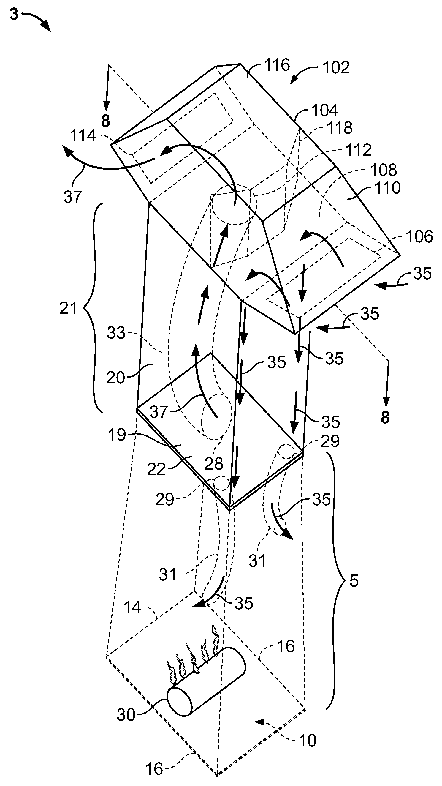
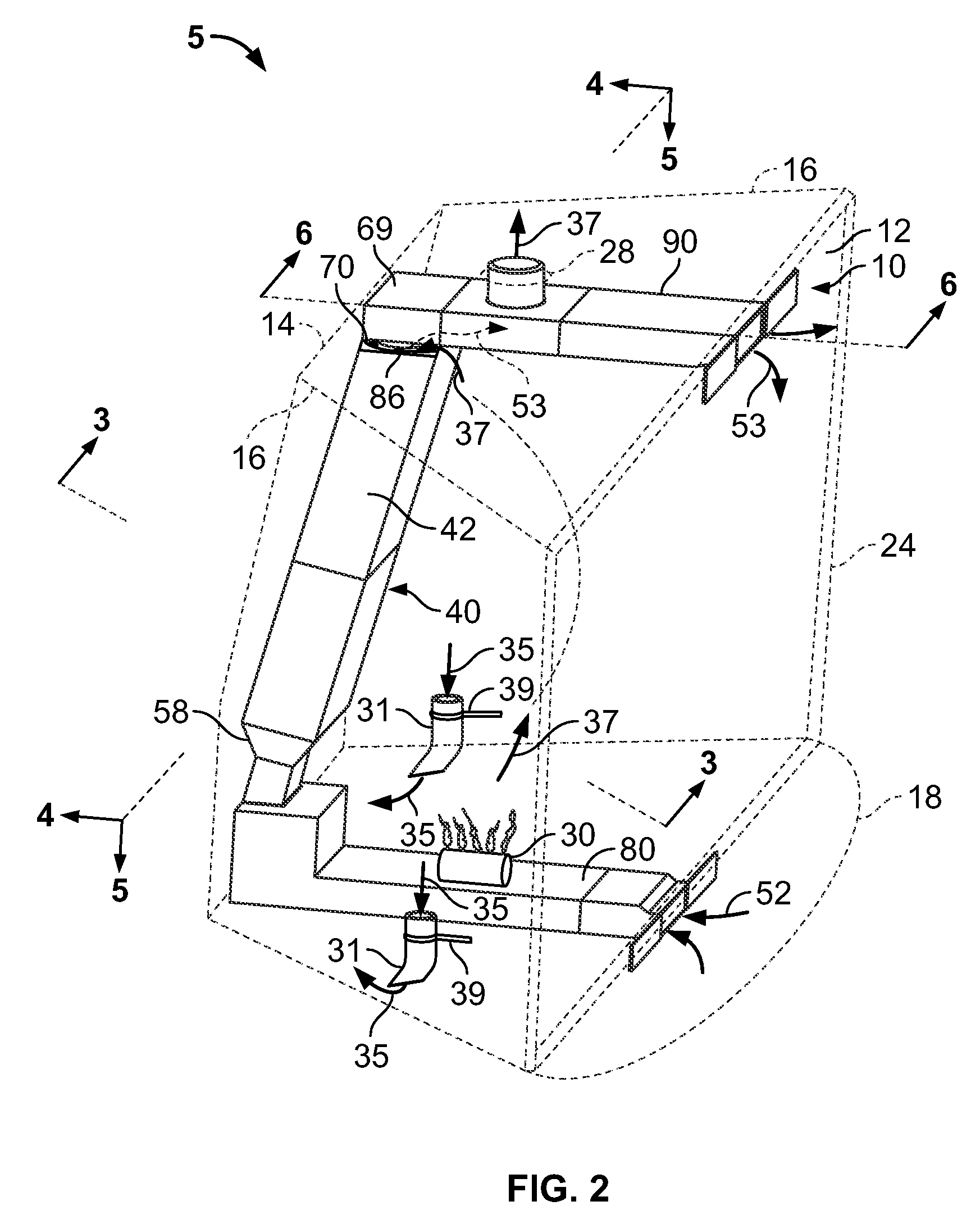
[0030]In FIGS. 1, 2 and 2A, there is shown a perspective view (and an exploded perspective view in FIG. 2A) of a fireplace 5 comprising a combustion chamber 10 having a front opening 12 (FIG. 2), a back wall 14, a pair of side walls 16, a hearth 18, and a chimney 21 including a chimney flue 20 connected to the top portion of the combustion chamber 10 by a throat or chimney opening 19. Combustion gases 37 produced in combustion chamber 10 are discharged through the chimney flue 20 by way of the throat or chimney opening 19, and then through a chimney cap 102. In one embodiment, fireplace venting system 3 conveys relatively cold outside air or combustion air 35 through chimney cap 102 and then through chimney flue 20 to combustion chamber 10, as will be discussed in further detail below.

[0031]FIGS. 1 and 2 further shows a suitable type of gas log burner 30 for producing heat energy that is supplied with heating gas from an external source. These gas log burners 30 are well known in th...


PUM


Abstract

A fireplace chimney cap includes a body having first and second apertures in fluid communication defining a first cavity therebetween. The first cavity is configured and disposed to receive combustion air through the first aperture, then through the second aperture for delivery to a fireplace combustion chamber. The body has third and fourth apertures in fluid communication defining a second cavity therebetween. The second cavity is configured and disposed to receive combustion gases from the fireplace combustion chamber through the third aperture, then through the fourth aperture for exhausting exterior of the body. The first and second cavities are fluidly separated from each other. The first and fourth apertures are configured and disposed to provide a pitot effect to more readily draw both combustion air into the first cavity and combustion gases into the second cavity in response to the first aperture disposed upwind and fourth aperture position disposed downwind.

Description

CROSS-REFERENCE TO RELATED APPLICATIONS[0001]This Application is a continuation in part of application Ser. No. 11 / 618,756, filed Dec. 30, 2006, Attorney Docket No. 2006-030, entitled “FIREPLACE HEAT EXCHANGER” and which is incorporated by reference in its entirety.FIELD OF THE INVENTION[0002]The present invention relates generally to fireplace accessories and, more particularly, to a fireplace chimney cap adaptable to a wide array of fireplace sizes and useful for improving the heating efficiency of a fireplace.BACKGROUND OF THE INVENTION[0003]Conventional fireplaces are inefficient sources of heat for the room in which they are located as the majority of the heat generated by the combustion process escapes through the chimney. Fireplace fires also require large volumes of combustion air, which if drawn from the interior space of the room, result in significant heat loss from the room as heated room air is also exhausted through the chimney. Cold air drafts in the interior space al...

Claims


Application Information

Patent Timeline
IPC IPC(8): F23J13/08
CPCF23J13/00F24B1/1808F23L17/02F23J2211/10
Inventor EBERHARDT, H. ALFREDWALLERICH, BERNARD T.CURLEY, GARY M.
Owner EBERHARDT H ALFRED
Why Eureka
Try Eureka