
Organometallic complex, and light-emitting element, light-emitting device and electronic device including the organometallic compex

a technology of organometallic complexes and light-emitting elements, which is applied in the field of organometallic complexes, can solve the problems of poor red color purity and disadvantages of organometallic complexes in color reproducibility for full-color display applications, and achieve high emission efficiency, high luminous efficiency, and high emission efficiency

Active Publication Date: 2008-07-03
SEMICON ENERGY LAB CO LTD
View PDF9 Cites 124 Cited by
  • Summary
  • Abstract
  • Description
  • Claims
  • Application Information

AI Technical Summary

Benefits of technology

[0013]The organometallic complex disclosed in Reference 2 emits orange-red light, which makes the purity of red color poor; accordingly, this organometallic complex is disadvantage in color reproducibility for application to a full-color display or the like. In contrast, in a case of an organometallic complex that emits dark red light, that is, light having an extremely long emission wavelength, although the organometallic complex is advantageous in terms of color reproducibility, the luminous efficiency (cd / A) thereof decreases.
[0047]Further, by using the organometallic complex of the present invention, it is possible to obtain a light-emitting device and an electronic device that not only obtain effect of the organometallic complex of the present invention and the light-emitting element including it but also achieve low power consumption.

Problems solved by technology

The organometallic complex disclosed in Reference 2 emits orange-red light, which makes the purity of red color poor; accordingly, this organometallic complex is disadvantage in color reproducibility for application to a full-color display or the like.

Method used


Image

  • Organometallic complex, and light-emitting element, light-emitting device and electronic device including the organometallic compex
  • Organometallic complex, and light-emitting element, light-emitting device and electronic device including the organometallic compex
  • Organometallic complex, and light-emitting element, light-emitting device and electronic device including the organometallic compex

Examples


embodiment mode 1

[0076]Embodiment Mode 1 will describe the organometallic complex of the present invention.

[0077]An organometallic complex of the present invention is formed by ortho-metalation of a dibenzo[f,h]quinoxaline derivative represented by the following general formula (G0) with a metal ion of Group 9 or Group 10.

[0078]In the formula, Ar represents an aryl group having 6 to 25 carbon atoms; R1 represents any one of hydrogen, an alkyl group having 1 to 4 carbon atoms, and an alkoxy group having 1 to 4 carbon atoms; R2 to R8 each represent any one of hydrogen, an alkyl group having 1 to 4 carbon atoms, an alkoxy group having 1 to 4 carbon atoms, and a halogen group; and at least one of pairs R3 and R4, R4 and R5, and R5 and R6 may be bound to each other to form a ring.

[0079]Hereinafter, explanation will be made on synthetic methods of the dibenzo[f,h]quinoxaline derivative represented by the general formula (G0) separately for each of the cases where R1 in the general formula (G0) is an alkyl...

embodiment mode 2

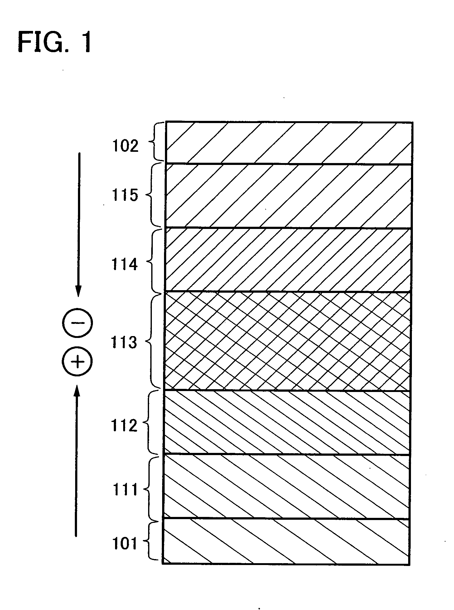
[0107]Embodiment Mode 2 will describe a mode of a light-emitting element that includes the organometallic complex of the present invention, described in Embodiment Mode 1, as a light-emitting substance with reference to FIG. 1.

[0108]FIG. 1 illustrates a light-emitting element including a light-emitting layer 113 between a first electrode 101 and a second electrode 102. The light-emitting layer 113 includes the organometallic complex of the present invention as described above in Embodiment Mode 1.

[0109]By applying voltage to such a light-emitting element, holes injected from the first electrode 101 and electrons injected from the second electrode 102 are recombined with each other in the light-emitting layer 113 to bring the organometallic complex of the present invention to an excited state. Light is emitted when the organometallic complex in the excited state returns to the ground state. The organometallic complex of the present invention thus functions as a light-emitting substan...

embodiment mode 3

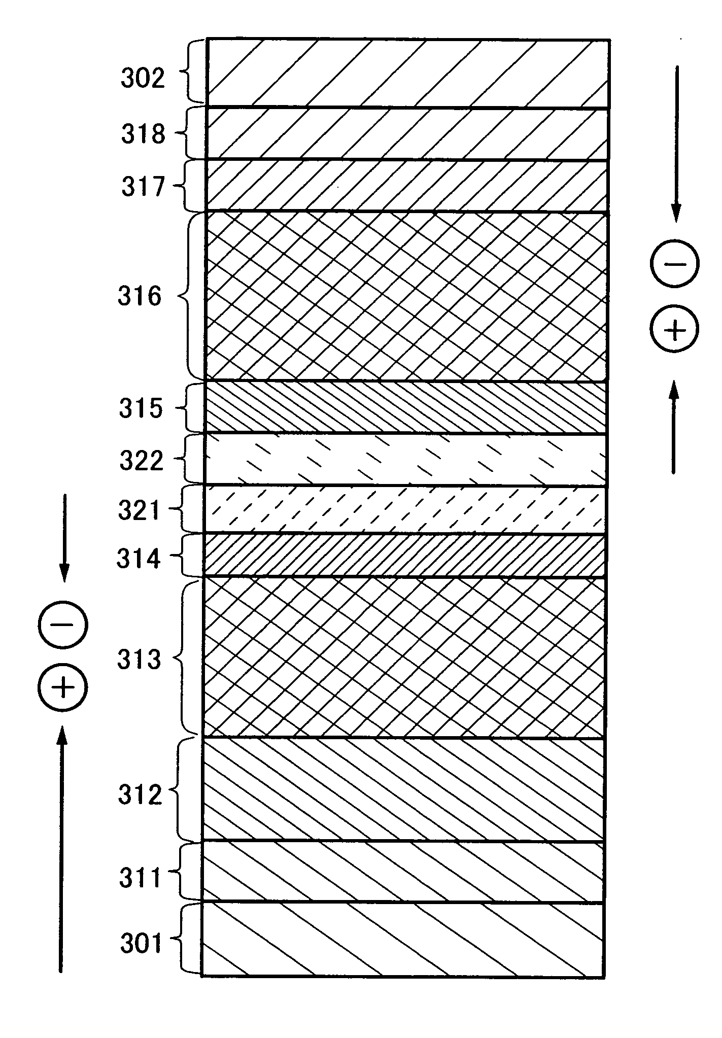
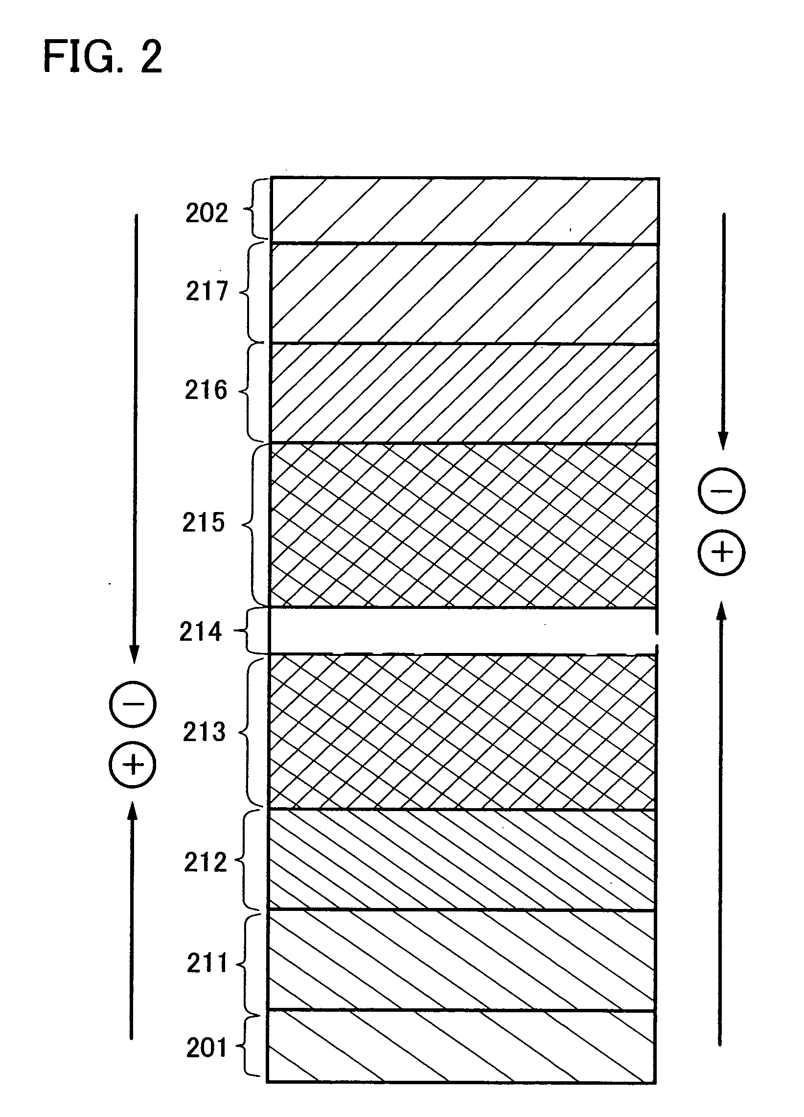
[0131]The light-emitting element of the present invention may have a plurality of light-emitting layers. A plurality of light-emitting layers are provided and then each of them emits light. Accordingly, light that is a combination of light emitted from the plurality of light-emitting layers can be obtained; for example, white light can be obtained. In Embodiment Mode 3, a light-emitting element having a plurality of light-emitting layers will be described with reference to FIG. 2.

[0132]In FIG. 2, a first light-emitting layer 213 and a second light-emitting layer 215 are provided between a first electrode 201 and a second electrode 202. Light that is a combination of light emitted from the first light-emitting layer 213 and light emitted from the second light-emitting layer 215 are mixed can be obtained. A separation layer 214 is preferably formed between the first light-emitting layer 213 and the second light-emitting layer 215.

[0133]When voltage is applied so that the potential of ...


PUM

PropertyMeasurementUnit
internal quantum efficiencyaaaaaaaaaa
temperatureaaaaaaaaaa

Abstract

An object is to provide an organometallic complex that can emit red light. Another object is to provide an organometallic complex having high emission efficiency. Still another object is to provide an organometallic complex that can emit red light with high luminous efficiency. The present invention provides an organometallic complex having a structure represented by the following general formula (G1′).In the formula, Ar represents an aryl group having 6 to 25 carbon atoms; R1 represents any one of hydrogen, an alkyl group having 1 to 4 carbon atoms, and an alkoxy group having 1 to 4 carbon atoms; R2 to R8 each represent any one of hydrogen, an alkyl group having 1 to 4 carbon atoms, an alkoxy group having 1 to 4 carbon atoms, and a halogen group; at least one of pairs R3 and R4, R4 and R5, and R5 and R6 may be bound to each other to form a ring; and M represents a central metal of Group 9 elements and Group 10 elements.

Description

BACKGROUND OF THE INVENTION[0001]1. Field of the Invention[0002]The present invention relates to an organometallic complex. In particular, the present invention relates to an organometallic complex that is capable of converting a triplet excited state into luminescence. Furthermore, the present invention relates to a light-emitting element, a light-emitting device, and an electronic device that include the organometallic complex.[0003]2. Description of the Related Art[0004]Organic compounds are brought into an excited state by the absorption of light. Through this excited state, various reactions (photochemical reactions) are caused in some cases, or luminescence is generated in some cases. Therefore, various applications of the organic compounds are made.[0005]As one example of the photochemical reactions, a reaction of singlet oxygen with an unsaturated organic molecule (oxygen addition) is known (refer to Reference 1: Haruo INOUE, et al., Basic Chemistry Course PHOTOCHEMISTRY I (...

Claims


Application Information

Patent Timeline
Patent Type & Authority Applications(United States)
IPC IPC(8): C09K11/61C07D237/26H10K99/00
CPCC07F15/0033Y10S428/917H01L51/0085C07F15/0086H10K85/342C07F15/00C07F17/02C07F19/00C09K11/06
Inventor INOUE, HIDEKOSEO, SATOSHIOHSAWA, NOBUHARU
Owner SEMICON ENERGY LAB CO LTD
Learn More