Multi-Band Loop Antenna
a loop antenna and multi-band technology, applied in the direction of resonant antennas, elongated active element feeds, radiating element structural forms, etc., can solve the problem that antennas often do not operate on multiple frequency bands, and achieve excellent performance characteristics and compact footprint
- Summary
- Abstract
- Description
- Claims
- Application Information
AI Technical Summary
Benefits of technology
Problems solved by technology
Method used
Image
Examples
first embodiment
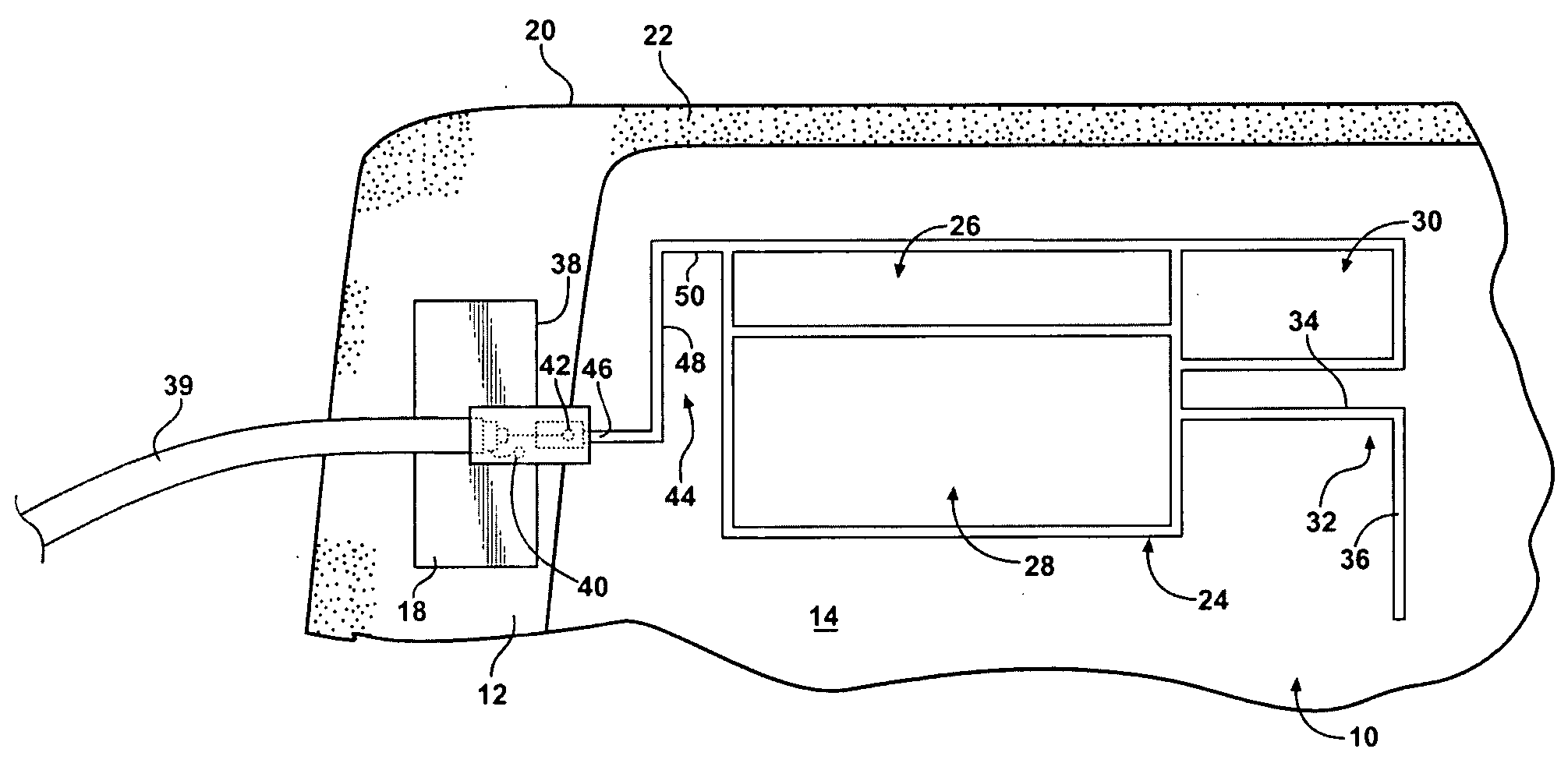
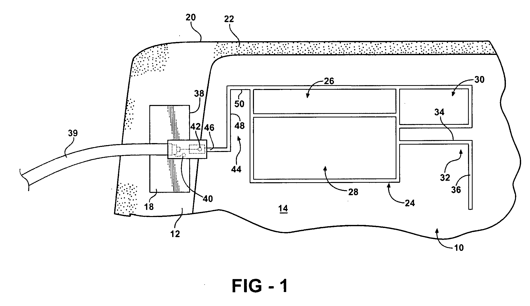
[0023]As stated above, the antenna 10 operates in multiple frequency bands. Particularly, the antenna 10 defined herein effectively radiates in a first frequency band, a second frequency band, and a third frequency band. Said another way, the antenna 10 exhibits an acceptable return loss and voltage standing wave ratio (VSWR) in a range of frequencies defining the first, second, and third frequency bands.
[0024]The antenna 10 is suitable for both transmitting and receiving linearly polarized RF signals. The antenna 10 is particularly suited for transmitting and receiving vertically polarized RF signals, which are commonly used in cellular / mobile communications networks.
[0025]The antenna 10, as described herein, preferably radiates in frequency bands utilized for cellular / mobile communications networks. Specifically, the first frequency band ranges from 824 MHz to 940 MHz, the second frequency band ranges from 1850 MHz to 1990 MHz, and the third frequency band ranges from 1920 MHz to ...
second embodiment
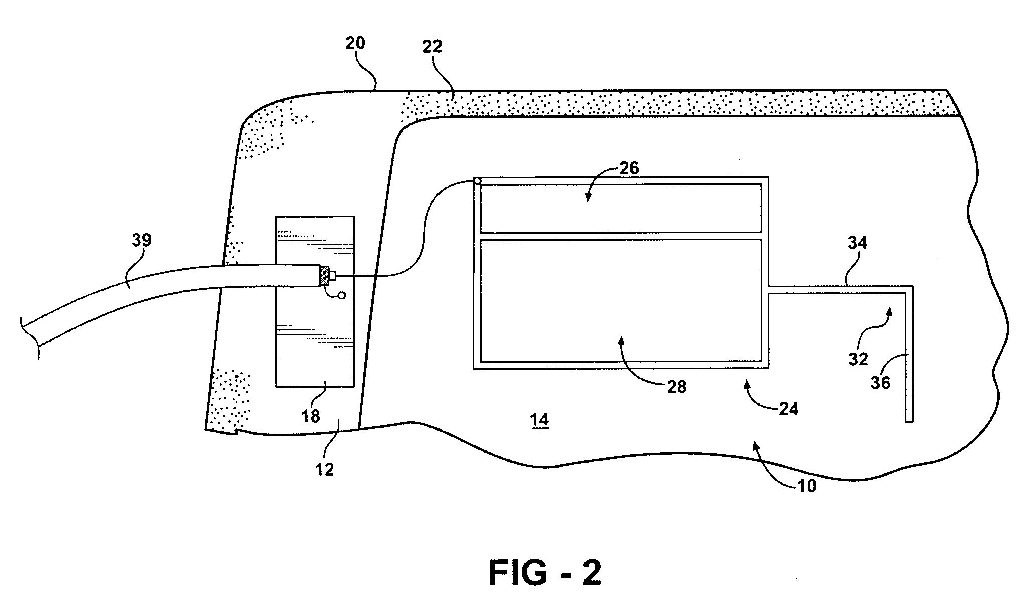
[0047]However, the connecting segment 44 could be implemented as a single segment (not shown) extending straight or diagonally from the second terminal 42 to the loops 26, 28, 30. Furthermore, the connecting segment 44 may be omitted altogether, as is the case in the second embodiment shown in FIG. 2.
[0048]As can be seen in FIGS. 3-9 the antenna 10 of the first embodiment produces excellent performance characteristics. In the first, second, and third frequency bands, the antenna 10 produces a return loss of over 10 dB with a voltage standing wave ratio (VSWR) of under 2:1. In the second and third frequency bands, the antenna 10 produces a return loss of over 10 dB with a VSWR around or under 2:1. FIGS. 5-9 show the antenna 10 provides overall good omnidirectionality characteristics in the azimuth plane.
PUM
 Abstract
Description
Claims
Application Information
 - R&D
- Intellectual Property
- Life Sciences
- Materials
- Tech Scout
- Unparalleled Data Quality
- Higher Quality Content
- 60% Fewer Hallucinations
Browse by: Latest US Patents, China's latest patents, Technical Efficacy Thesaurus, Application Domain, Technology Topic, Popular Technical Reports.
© 2025 PatSnap. All rights reserved.Legal|Privacy policy|Modern Slavery Act Transparency Statement|Sitemap|About US| Contact US: help@patsnap.com


