Eureka AIR delivers breakthrough ideas for toughest innovation challenges, trusted by R&D personnel around the world.

Adaptive energy absorption system for a vehicle seat

a technology of energy absorption and vehicle seats, which is applied in the direction of shock absorbers, pedestrian/occupant safety arrangements, elastic dampers, etc., can solve the problems of inability to adjust and stroke energy absorption or stroking profiles as a function of occupant weight, real-time environmental measurements, and inability to adjust and stroke energy absorption profiles. , to achieve the effect of minimizing occupant motion, enhancing comfort, and effectively reducing load into the occupant's body

Active Publication Date: 2008-07-03
INNOVITAL LLC +1
View PDF35 Cites 157 Cited by
  • Summary
  • Abstract
  • Description
  • Claims
  • Application Information

AI Technical Summary

Benefits of technology

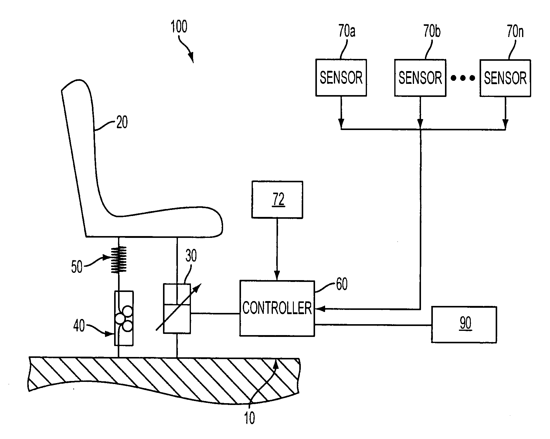
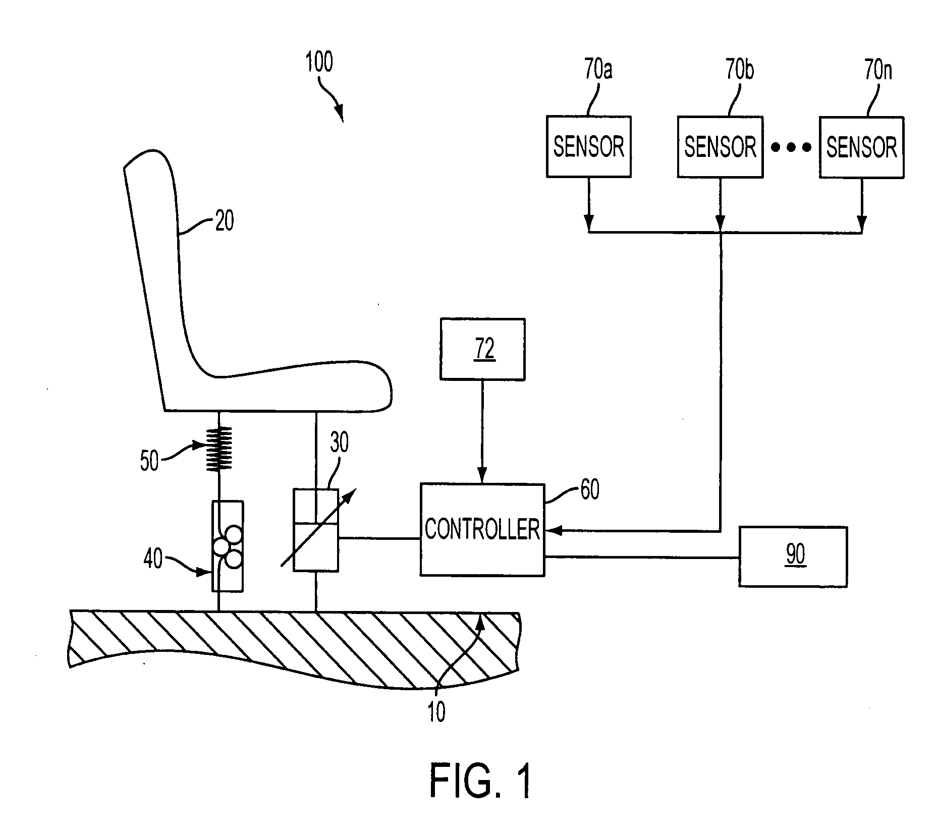
[0010]The adaptive energy absorption system of the invention may further comprise, in addition to the VPEA, a controller (e.g., a single-mode or multi-mode controller), and one or more sensors for measuring, among other things, force, acceleration, velocity, strain, displacement, etc. The adaptive energy absorption system may also interface with existing vehicle sensors (e.g., an aircraft altimeter to measure sinkrate). Moreover, the adaptive energy absorption system may additionally comprise a fixed profile energy absorber (FPEA) and / or a stiffness element (e.g., to supplement VPEA force and aid in vibration isolation) alone or in combination with the VPEA. In one implementation, one or more components of the adaptive energy absorption system may be powered by a power source independent of the vehicle (e.g., via one or more batteries). The independent power source enables the system to continue to function in the event of a loss of vehicle power due to, for example, a shock event, or for any other reason.
[0011]According to an aspect of the invention, the VPEA may respond to changing environmental stimuli such as occupant weight, occupant attitude, load level, or other stimuli, to effectively mitigate loads into the occupant's body. During normal operating conditions, for example, the VPEA may be automatically adjusted in real-time to minimize occupant motion based upon a known occupant weight (e.g., automatically sensed or manually adjusted) and known vibration levels (e.g., from sensors). Limiting seat motion provides the advantages of enhancing comfort and reducing fatigue for the occupant of the vehicle seat. During an extreme motion event (e.g., a shock event), motion sensors may trigger the controller in to a secondary mode, wherein the VPEA may be automatically adjusted to keep body loads (pelvic loads, spinal loads, etc.) within acceptable levels.
[0012]One advantage provided by the invention is that the controller may automatically adjust the VPEA in real-time to optimize occupant body loads based on a feedback control algorithm. For example, sensors for measuring VPEA stroke (e.g., Linear Variable Differential Transformers (LVDTs)) as well as accelerometers on the vehicle floor, vehicle seat, and / or occupant helmet (or other wearable article) may provide measurements which are fed back to the control algorithm. The control algorithm may then use this sensor data to maintain body loads (e.g., lumbar force, chest accelerations, etc.) below injury limits.
[0015]Still yet another advantage provided by the invention is that real-time feedback control may be used to optimally control the VPEA to mitigate vibration due to normal vehicle operation; thereby enhancing comfort and reducing fatigue for the occupant. In one implementation, the same controller used for shock control may be utilized for vibration control. Alternatively, a multi-mode controller may be used that minimizes occupant vibration during normal operation, and then switches to a shock control mode during an extreme motion event. Once an extreme motion event is measured, the controller may switch to a shock control mode to prevent occupant injury.

Problems solved by technology

The minimization of shock load-induced injury is an important issue in seat suspension design.
Occupant spinal and pelvic injuries, for example, may result from harsh vertical / crash landings of aircraft, as well as from vertical shock of land and marine vehicles.
One drawback associated with these FLEAs, however, is that they were not adjustable and stroked at a factory-established, constant load throughout their entire operating range.
One drawback associated with FPEAs is that they are passive, meaning that they cannot adapt their energy absorption or stroking profiles as a function of occupant weight, or as a function of real-time environmental measurements such as a vibration or shock load.
Seat suspension systems that utilize FPEAs suffer from these and other drawbacks.

Method used


Image

  • Adaptive energy absorption system for a vehicle seat
  • Adaptive energy absorption system for a vehicle seat
  • Adaptive energy absorption system for a vehicle seat

Examples


Embodiment Construction

[0065]An adaptive energy absorption system is disclosed for use with any type of vehicle seats including, but not limited to, aircraft (e.g., rotorcraft, fixed wing, etc.) seats, land vehicle seats (e.g., seats for heavy-duty military, agricultural, and construction vehicles, etc.), marine vehicle seats, or seats for other vehicles that may experience vertical (or other) shock loads, or that may be exposed to varying levels of vibration during normal operating conditions.

[0066]With particular reference to FIG. 1, adaptive energy absorption system 100 is provided for a vehicle seat 20. In one implementation, vehicle seat 20 may comprise an existing vehicle seat, and one or more of the components of system 100 (as disclosed herein) may be retrofit to vehicle seat 20. Alternatively, vehicle seat 20 along with one or more components of system 100 may be provided together as an integral system for installation in a vehicle.

[0067]According to an aspect of the invention, an adaptive energy...


PUM


Abstract

An adaptive energy absorption system for a vehicle seat is disclosed, utilizing an adaptive energy absorber or variable profile energy absorber (VPEA) for mitigating occupant injury due to extreme vehicle movement (e.g., during a vehicle shock event), and / or for mitigating vibration experienced by an occupant of the vehicle seat during normal vehicle operating conditions. Various configurations of dual-goal energy absorption apparatuses using both VPEA and fixed load energy absorbers (FLEAs) that enable both shock mitigation and vibration isolation are disclosed. A semi-active control absorption system, comprising a VPEA and FPEA configured to work in series, is also disclosed.

Description

CROSS-REFERENCE TO RELATED APPLICATIONS[0001]This application claims priority to U.S. Provisional Patent Application No. 60 / 905,842, filed Mar. 9, 2007, and is a continuation-in-part of U.S. patent application Ser. No. 11 / 670,761, filed Feb. 2, 2007, which claims priority to U.S. Provisional Patent Application No. 60 / 809,386, filed May 31, 2006, all of which are hereby incorporated by reference herein in their entirety. This application also incorporates by reference herein in its entirety, U.S. patent application Ser. No. 11 / 670,773, filed Feb. 2, 2007, which claims priority to U.S. Provisional Patent Application No. 60 / 809,386, filed May 31, 2006.STATEMENT REGARDING FEDERALLY SPONSORED RESEARCH OR DEVELOPMENT[0002]Work relating to the subject matter of this patent application may have been performed with U.S. Government support under Contract No. N00421-06-C-0006, awarded by Naval Air Warfare Center Aircraft Division (Pax River, Md.). The U.S. Government may have certain rights in...

Claims


Application Information

Patent Timeline
Patent Type & Authority Applications(United States)
IPC IPC(8): F16F9/53F16F9/504B60N2/42
CPCB60N2/4242B60N2/42736F16F9/53B60N2/508B60N2/522B60N2/501
Inventor HIEMENZ, GREGORY J.HU, WEIWERELEY, NORMAN M.CHEN, PETER CHE-HUNG
Owner INNOVITAL LLC
Why Eureka
Eureka Blog
Learn More