Image processing apparatus and image processing method
a technology of image processing and image processing, applied in the direction of digital output to print units, instruments, digitally marking record carriers, etc., can solve the problem of not being able to output an image in normal mode, and the output image is not good
- Summary
- Abstract
- Description
- Claims
- Application Information
AI Technical Summary
Benefits of technology
Problems solved by technology
Method used
Image
Examples
first embodiment
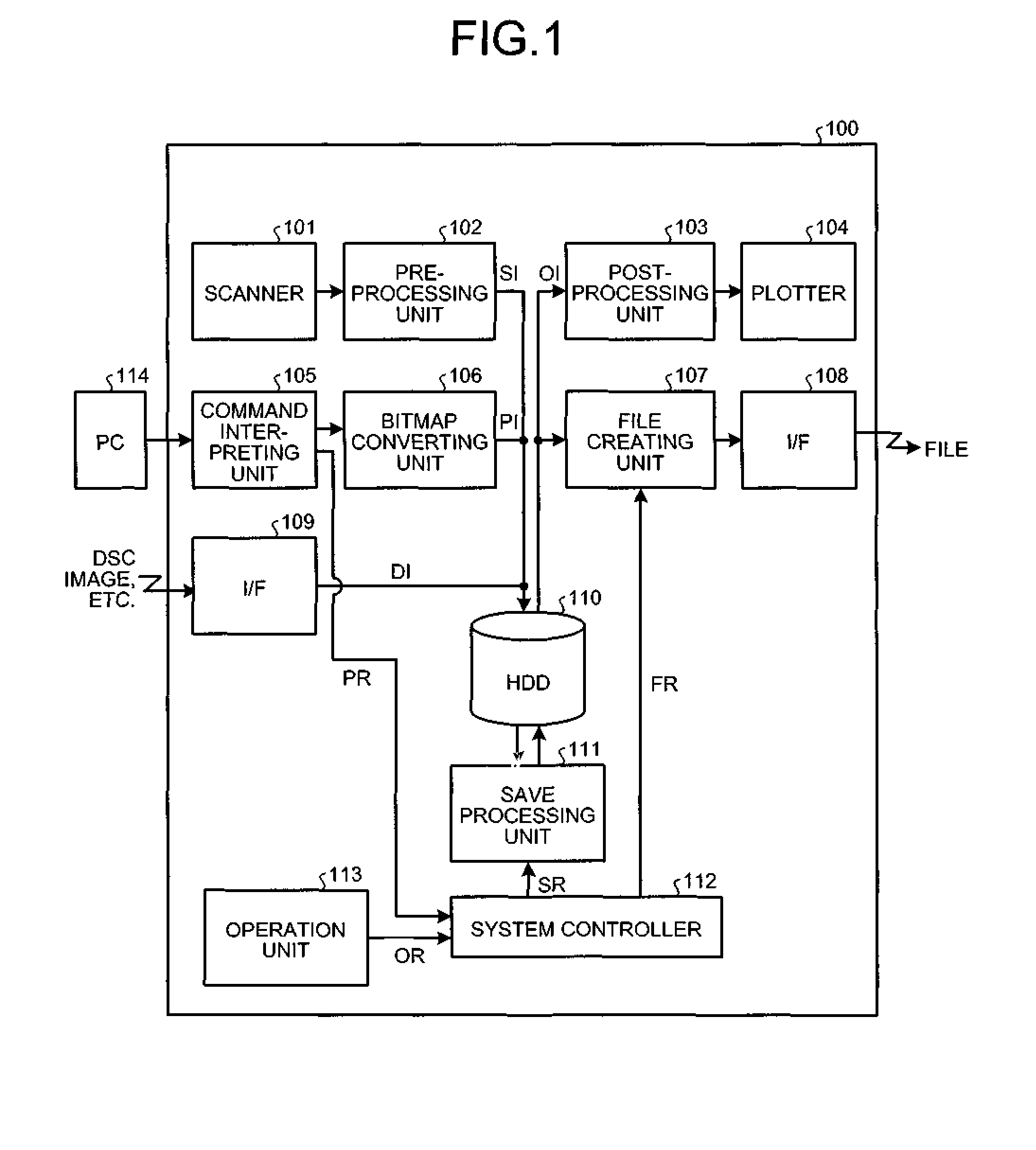
[0035]FIG. 1 is a block diagram of an image processing apparatus 100 according to the present invention. The image processing apparatus 100 receives an image signal from a personal computer (PC) 114 or through any one of a scanner 101 and an interface (I / F) 109. The image signal is processed, and then output to either a plotter 104 or an I / F 108.
[0036]Upon receiving an image signal from the scanner 101, a pre-processing unit 102 processes the image signal into an image signal SI in a manner as described in detail later. The image signal SI is stored in a hard disk drive (HDD) 110.
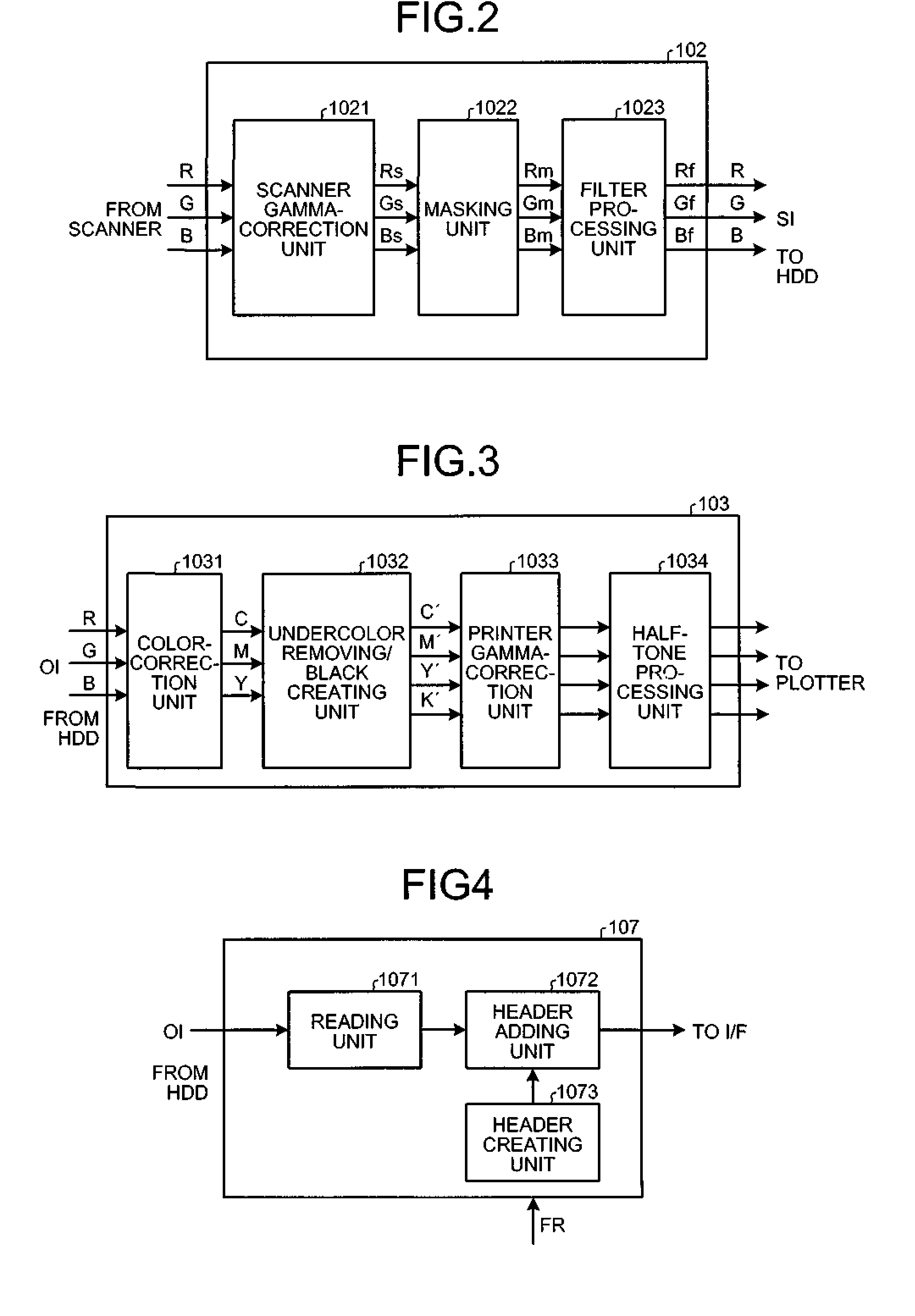
[0037]FIG. 2 is a block diagram of the pre-processing unit 102. The image signal received from the scanner 101 is converted by a scanner gamma-correction unit 1021 from a linear-reflectance signal into a linear-density signal.
[0038]The scanner gamma-correction unit 1021 converts red (R), green (G), and blue (B) signals into Rs, Gs, and Bs signals by referring to a one-dimensional table. A masking unit 1022 ...
second embodiment
[0056]FIG. 6 is a block diagram of a save processing unit 121 according to the present invention. The save processing unit 121 includes an edge determining unit 1112, a density-decrease gamma converting unit 1113, and a selector 1114. The edge determining unit 1112 performs edge determination. FIG. 7 is a block diagram of the edge determining unit 1112. When the edge determining unit 1112 receives image data, a binarization unit 1115 binarizes the image data by using a threshold TH, and then a pattern matching circuit 1116 detects edges (contours) in the image data. A value of the threshold TH is decided depending on density of target letters for the edged determination, and is set to, for example, 32 (white: 255, black: 0). FIG. 8 is a schematic diagram of a detection pattern used by the pattern matching circuit 1116. The pattern matching circuit 1116 detects edges from a reference pixel j and its surrounding pixels by using the following Equation 4:
if(j&&g&&k&&m)=1, then pixel j=n...
third embodiment
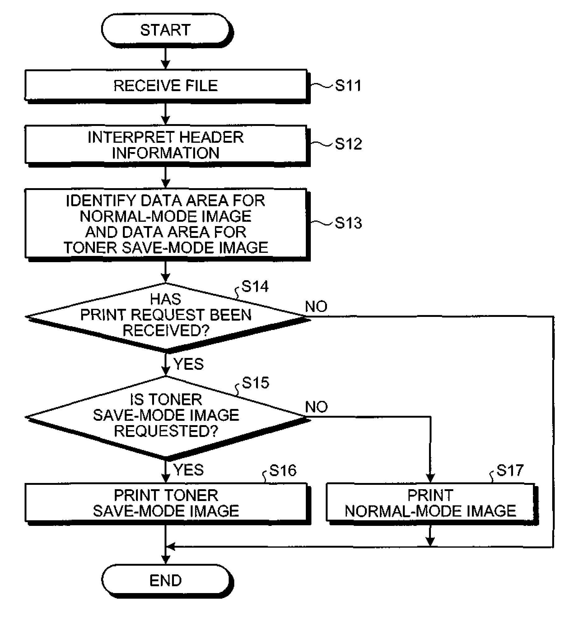
[0061]An image processing apparatus according to the present invention is described below with reference to FIGS. 10 and 11. FIG. 10 is a block diagram of a file creating unit 137. The file creating unit 137 includes a first reading unit 1078, a second reading unit 1079, a joining unit 1081, the header adding unit 1072, and the header creating unit 1073. The first reading unit 1078 reads normal-mode image data, and the second reading unit 1079 reads toner save-mode image data from the HDD 110. The joining unit 1081 joins together the normal-mode image data and the toner save-mode image data. The header adding unit 1072 adds a header created by the header creating unit 1073 to the joined image data, thereby creating an image file in a predetermined format. The header created by the header creating unit 1073 contains information concerning each of the normal-mode image and the toner save-mode image (data size, capacity, start address, and color mode). As a result, the file creating un...
PUM
 Abstract
Description
Claims
Application Information
 - R&D
- Intellectual Property
- Life Sciences
- Materials
- Tech Scout
- Unparalleled Data Quality
- Higher Quality Content
- 60% Fewer Hallucinations
Browse by: Latest US Patents, China's latest patents, Technical Efficacy Thesaurus, Application Domain, Technology Topic, Popular Technical Reports.
© 2025 PatSnap. All rights reserved.Legal|Privacy policy|Modern Slavery Act Transparency Statement|Sitemap|About US| Contact US: help@patsnap.com


