
Inkjet image forming method and apparatus, and ink composition therefor

Inactive Publication Date: 2008-06-19
FUJIFILM CORP
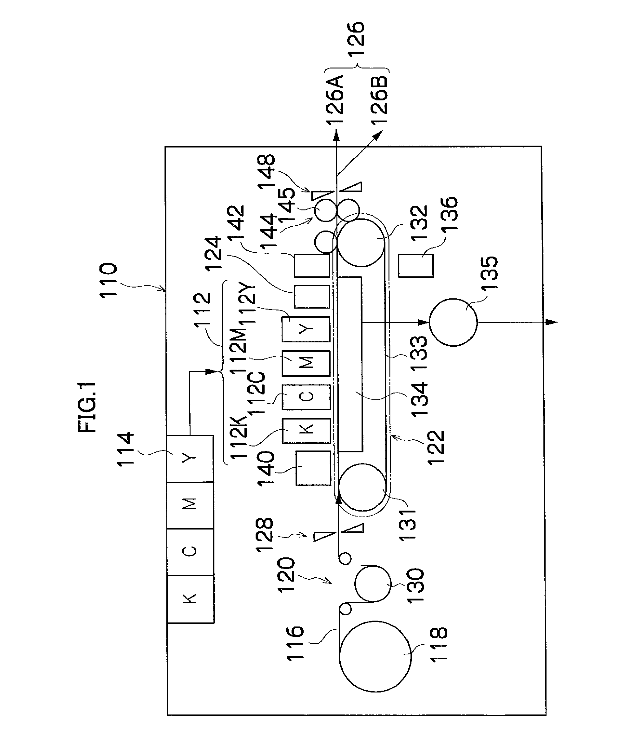
View PDF10 Cites 34 Cited by
  • Summary
  • Abstract
  • Description
  • Claims
  • Application Information

AI Technical Summary

Benefits of technology

[0015]The present invention has been contrived in view of these circumstances, an object thereof being to provide an inkjet image forming method, an inkjet image forming apparatus and an ink composition whereby the nozzle cleaning characteristics, the ejection stability, the ink fixing characteristics, and the wear resistance are all improved.

Problems solved by technology

Moreover, there are problems in relation to variation in the ejection direction of the ink droplets, and it is necessary to take account of the fixing characteristics and the wear resistance characteristics of the ink on the recording medium.
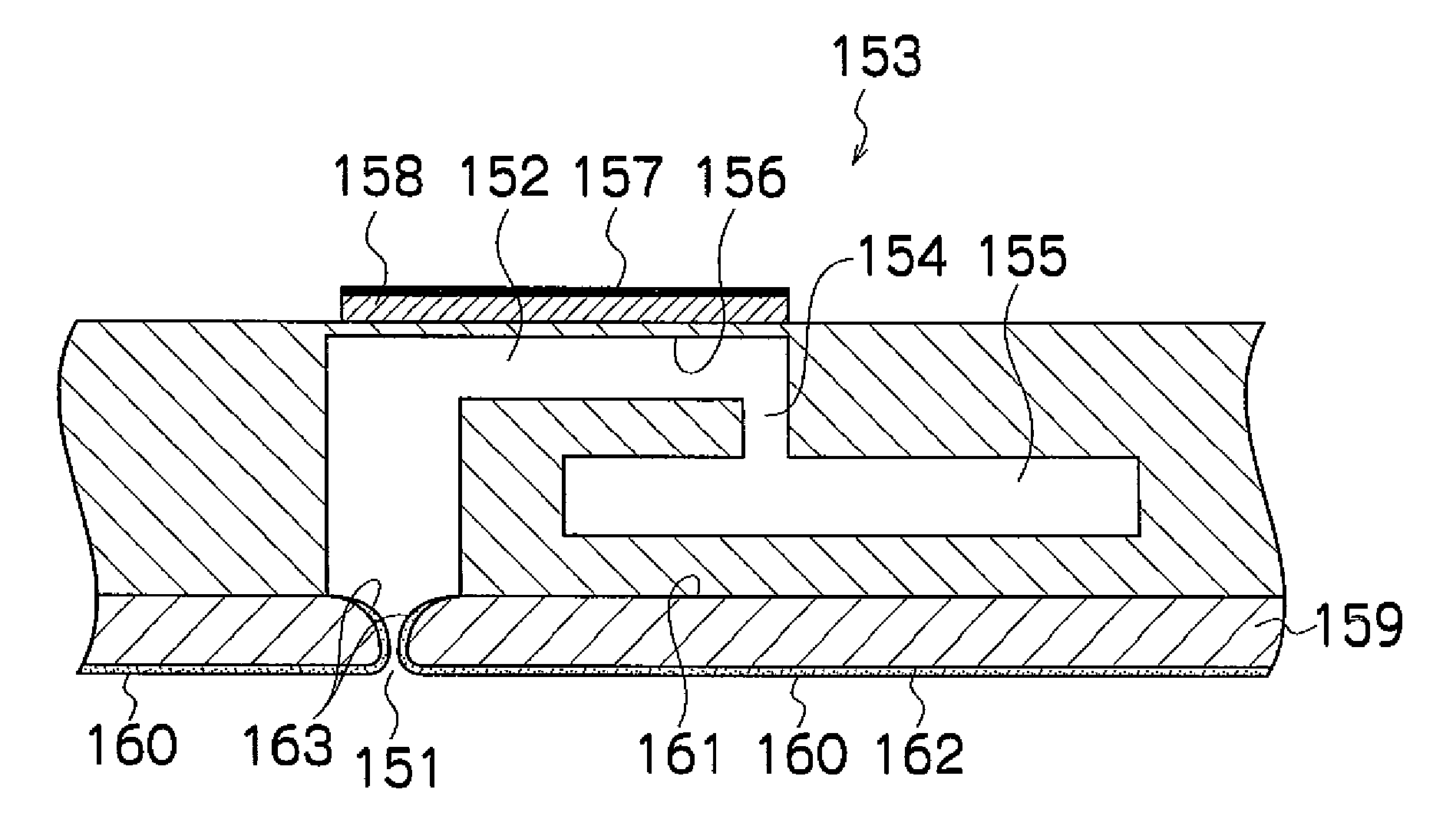
However, in the technology disclosed in Japanese Patent Application Publication No. 05-116327, it is difficult to adequately prevent soiling caused by residual ink in the vicinity of the nozzle holes.
Therefore, if used for a long period of time, residual ink accumulates in the vicinity of the nozzle holes, ejection characteristics deteriorate, and the cleaning load increases.
In this case, problems may occur in that bubbles (i.e., air bubbles) are drawn in, the ejection direction of the ink droplet varies due to the effects of the bubbles, or ink ejection may become impossible.
In the ink composition described in Japanese Patent Application Publication No. 2001-030616, the wear resistance of the image is improved, but since the ink contains a resin component having film forming characteristics, then the ink forms a film if residual ink is left in the vicinity of the nozzle holes, resulting in the degradation of the ink ejection characteristics.
Moreover, a problem also arises in that the cleaning load is increased.
Furthermore, if polymer particles are added in excessive quantity in order to improve the wear resistance, the ejection reliability deteriorates markedly and the cleaning load also increases markedly.
However, there are cases where the ink meniscus retreats inside the nozzle holes, and it is difficult to resolve the problem of the variation in the ink ejection direction.
However, in order to ensure the resistance to wear, it is necessary to include a large amount of inorganic oxide, and therefore it is difficult to achieve both the wear resistance and the ejection stability, at the same time.
Moreover, it is difficult to resolve the problem of the variation in the ink ejection direction caused by the retreat of the meniscus surface.
As described above, in the apparatus or ink composition described in Japanese Patent Application Publication Nos. 05-116327, 2001-030616, 06-008416 and 09-286941, although it is possible to improve the nozzle cleaning characteristics, the variation in the ejection direction, or the wear resistance and fixing characteristics, it is difficult to improve all of these factors.

Method used


Image

  • Inkjet image forming method and apparatus, and ink composition therefor
  • Inkjet image forming method and apparatus, and ink composition therefor
  • Inkjet image forming method and apparatus, and ink composition therefor

Examples


examples

[0161]The present invention is described in more specific terms below with reference to practical examples.

Manufacture of Pigment Dispersion

(Pigment Dispersion A)

[0162]A block polymer of ABC (A:B:C=13:4:10 (mol ratio), number average molecular weight=3,000) type including methacrylic acid (A) / benzyl methacrylate (B) / ethoxy triethylene glycol methacrylate (C) was prepared as a polymer dispersant. Thereupon, 30 g of the block polymer (polymer dispersant) was mixed with 9 g of 45% aqueous solution of potassium hydroxide and 261 g of deionized water, making a total of 300 g, and this mixture was neutralized until a uniform 10% polymer solution was obtained. Next, 150 g of C.I. Pigment Red—122 and 550 g of deionized water were added to the whole amount of this polymer solution and mixed, and then agitated for 0.5 hour in a disperser machine, thereby yielding a preparatory mixture. Next, this preparatory mixture was introduced into a dual tank with an internal capacity of 2 liters, and wh...


PUM

PropertyMeasurementUnit
Temperatureaaaaaaaaaa
Particle sizeaaaaaaaaaa
Glass transition temperatureaaaaaaaaaa

Abstract

An inkjet image forming method of forming an image on a recording medium includes the step of ejecting an ink composition through a nozzle hole onto the recording medium so that the image is formed on the recording medium. The ink composition contains coloring material particles and polymer particles, the polymer particles including an anionic hydrophilic functional group, and having a minimum film forming temperature of not higher than 25° C. and a ratio Mv / Mn of a volume-average particle size Mv to a number-average particle size Mn of not less than 1 and not greater than 1.5; and the nozzle hole is provided in a nozzle plate which is uniformly coated with an ink repelling film on a front surface of the nozzle plate, an inner surface of the nozzle hole and a part of a rear surface of the nozzle plate surrounding the nozzle hole, the ink repelling film having properties to repel the ink composition.

Description

BACKGROUND OF THE INVENTION[0001]1. Field of the Invention[0002]The present invention relates to an inkjet image forming method and apparatus, and an ink composition used therein.[0003]2. Description of the Related Art[0004]An inkjet image forming apparatus has been known and used widely as a data output apparatus for outputting an image, document, or the like. The inkjet image forming apparatus has a print head which ejects ink through nozzles to form an image, document, or the like on a recording medium according to print data by driving corresponding actuators provided for the nozzles in accordance with the print data.[0005]As to such an inkjet image forming apparatus, in order to prevent deterioration of the ejection characteristics of the ink, it is necessary to carry out cleaning of the nozzles. Moreover, there are problems in relation to variation in the ejection direction of the ink droplets, and it is necessary to take account of the fixing characteristics and the wear resi...

Claims


Application Information

Patent Timeline
IPC IPC(8): G03G15/00B41J2/01B41M5/00B82Y30/00C09D11/00C09D11/322C09D11/328
CPCB41J2/14233B41J2/1433B41J2/155B41J2/1606B41J2/161B41J2/162G03G15/104B41J2/1631B41J2/1643B41J2002/14459B41J2002/14475B41J2202/07B41J2/1623
Inventor HOUJOU, HIROAKI
Owner FUJIFILM CORP
Learn More