
Device for connecting a kickstand to a bicycle

a technology for connecting devices and bicycles, which is applied in the field of bicycles, can solve problems such as troublesome process, device not aesthetically pleasing, and firm connection of kickstands to bicycles

Inactive Publication Date: 2008-06-19
CHUANG LOUIS
View PDF10 Cites 7 Cited by
  • Summary
  • Abstract
  • Description
  • Claims
  • Application Information

AI Technical Summary

Benefits of technology

[0008]The primary advantage of the device according to the present invention is firm interconnection of the first and second connective members because the block is fit in the cavity.

Problems solved by technology

This process is however troublesome.
Furthermore, the connection of the kickstand 5 to the bicycle is not firm.
Moreover, the device is not aesthetically pleasing.
This process is however troublesome.
Furthermore, the connection is not firm.
Moreover, the device is not aesthetically pleasing.

Method used


Image

  • Device for connecting a kickstand to a bicycle
  • Device for connecting a kickstand to a bicycle
  • Device for connecting a kickstand to a bicycle

Examples


Embodiment Construction

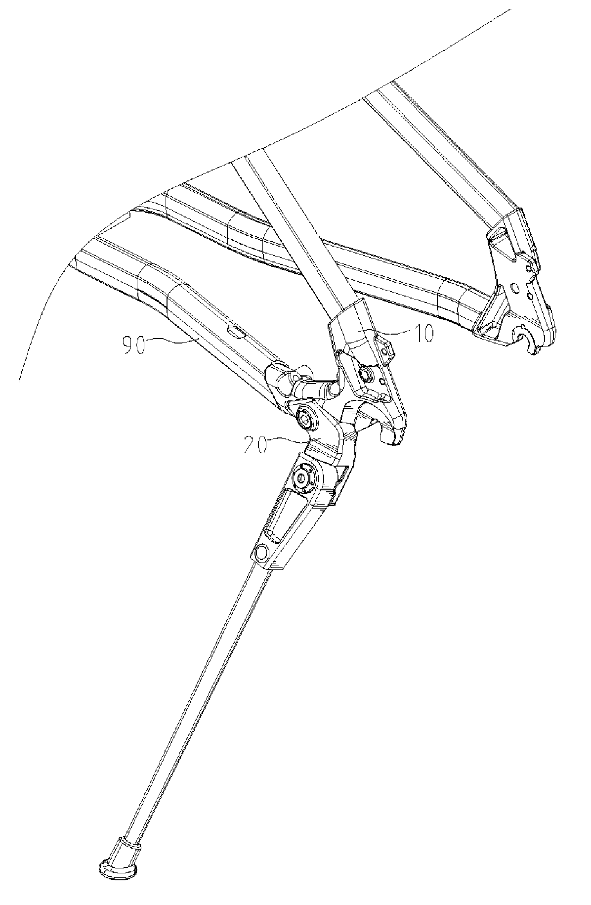
[0020]Referring to FIG. 1, there is shown a device for connecting a kickstand 21 (FIG. 2) to a bicycle according to a first embodiment of the present invention. The device includes a first connective member 10 and a second connective member 20 connected to the first connective member 20. The first connective member 10 is connected to a chain stay 90 and a seat stay. The kickstand 21 is pivotally connected to the second connective member 20.

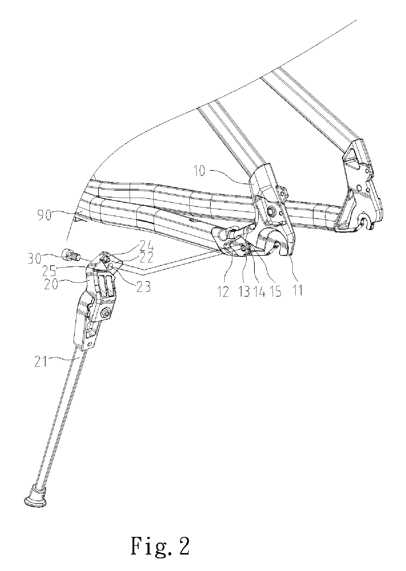
[0021]Referring to 2, the first connective member 10 is made of a bent form with a first end connected to the chain stay 90, a second end connected to the seat stay and a claw 11 formed between the first and second ends for holding a shaft of a rear wheel. The first connective member 10 is made with a first side and a second side located further from the rear wheel than the first side. The first connective member 10 includes a cavity 12 defined in the second side, a screw hole 13 defined in the floor of the cavity 12, a recess 14 defined in the fl...


PUM


Abstract

A device is disclosed for connecting a kickstand to a bicycle. The device includes a first connective member, a second connective member and a fastener. The first connective member is connected to a chain stay and a seat stay. The first connective member includes a claw formed thereon for holding a shaft of a rear wheel and a cavity defined therein. The kickstand is pivotally connected to the second connective member. The second connective member includes a block fit in the cavity so that the first and second connective members cannot be rotated with respect to each other. The fastener is used for fastening the first and second connective members to each other.

Description

BACKGROUND OF INVENTION[0001]1. Field of Invention[0002]The present invention relates to a bicycle and, more particularly, to a device for connecting a kickstand to a bicycle.[0003]2. Related Prior Art[0004]Disclosed in Taiwanese Patent Publication No. 226133 is a device for connecting a kickstand 5 to a bicycle. The device includes plates 2 and 3, a hooking element 9, two threaded bolts and two nuts. The kickstand 5 is pivotally connected to the plate 3. A chain stay 4 is sandwiched between the plates 2 and 3. The hooking element 9 includes a U-shaped body and two hooks 91 extending from the U-shaped body. A seat stay 4A is hooked by the hooks 91 of the hooking element 9. The U-shaped body of the hooking element 9 is sandwiched between the plates 2 and 3. The nuts are engaged with the threaded bolts that are inserted through the plates 2 and 3. The U-shaped body of the hooking element 9 is provided around one of the threaded bolts. Thus, the kickstand 5 is connected to the bicycle ...

Claims


Application Information

Patent Timeline
Patent Type & Authority Applications(United States)
IPC IPC(8): B62H1/00
CPCB62H1/02
Inventor CHUANG, LOUIS
Owner CHUANG LOUIS
Learn More