
System and method for interfacing with a microfluidic chip

Inactive Publication Date: 2008-06-05
CALIFORNIA INST OF TECH
View PDF48 Cites 53 Cited by
  • Summary
  • Abstract
  • Description
  • Claims
  • Application Information

AI Technical Summary

Benefits of technology

[0019]The present disclosure provides methods and devices for interfacing microfluidic chip systems with external fluidic systems. The interface described comprises primarily an “adapter”. The adapter has a simple

Problems solved by technology

Despite much progress in the field of microfluidics over the past several years, there have been no reported systems that address this world-to-chip interface problem in a general way.
This approach is suitable in applications where reagents are provided in a combinatorial manner or where a sample is analyzed in a combinatorial fashion, but is not useful for microfluidic chips that perform a small number of arbitrary syntheses and analyses.
While such technologies and other ultra-low dead-volume connectors make efficient use of reagents in microfluidic chips, they do not address the general problems of elimination of trapped air when delivering fluids to the microfluidic chip, and cleaning and drying of fluid lines.
Another limitation of reported microfluidic systems and technologies is that connections to external fluidic systems are impractical for commercial applications that involve frequent and repeated removal and assembly of microfluidic chips.
Glued and other permanent forms of connections are clearly not suitable in applications where swapping must occur.
Removable connections such as slip-on fittings or threaded fittings are superior, but removal and installation of the microfluidic chip can take considerable time if there are more than a couple of fittings.
In addition, manual attachment of numerous fittings introduces a significant possibility of error.
However, the use of such an open port provides the risk that the sample could be lost due to inaccuracies in flow rates, pressures, etc in the system.
However, depending on permeability and pressure, this can take a significant amount of time and slow down the microfluidic process.
Another situation where such a “vent” port is impractical is if a reactor portion of the microfluidic chip is filled with some intermediate compound.

Method used


Image

  • System and method for interfacing with a microfluidic chip
  • System and method for interfacing with a microfluidic chip
  • System and method for interfacing with a microfluidic chip

Examples


Embodiment Construction

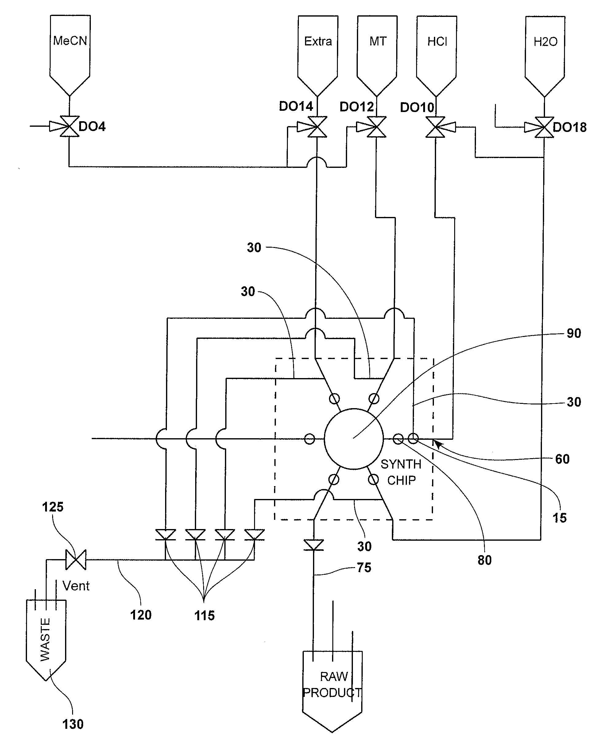
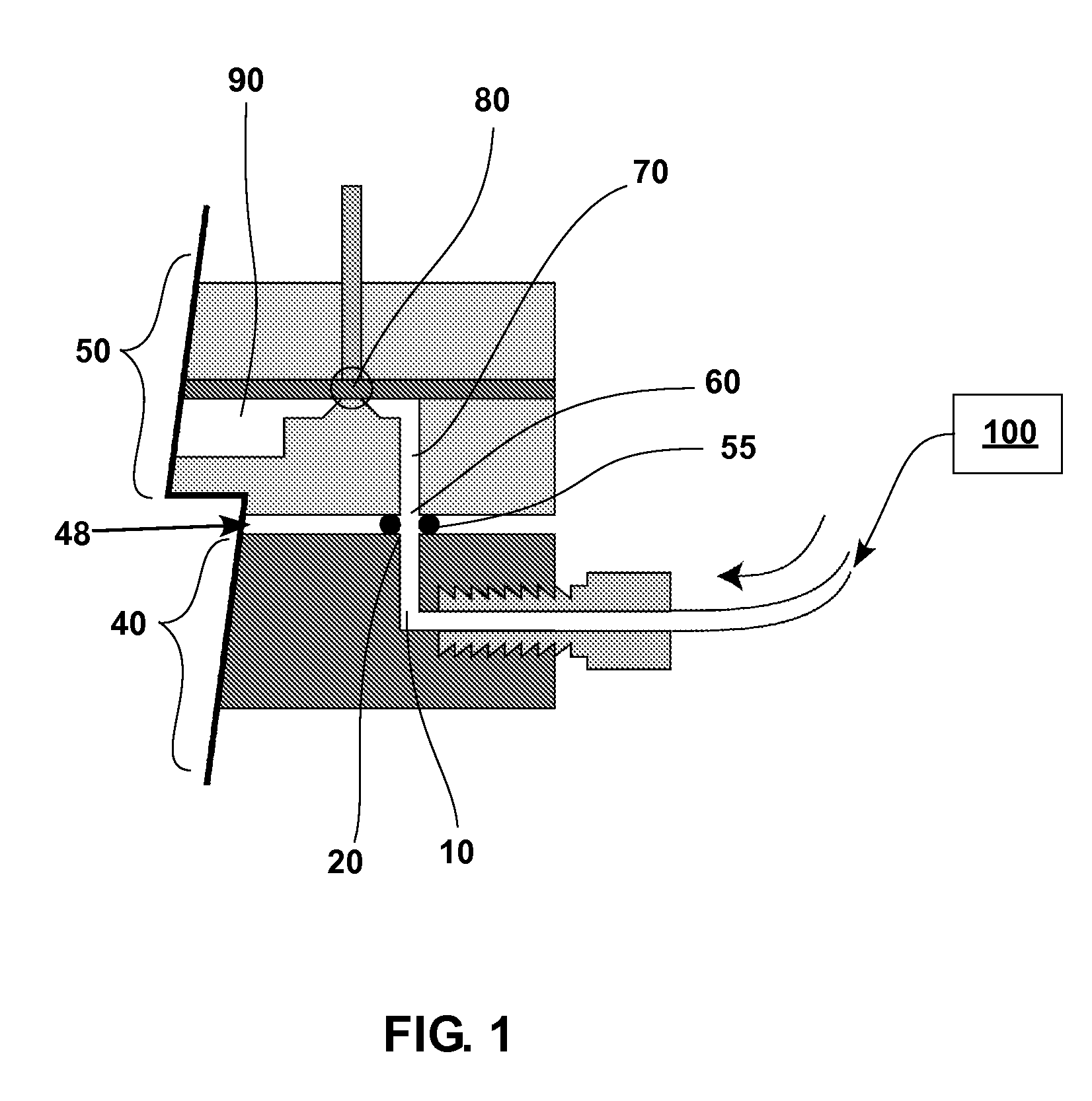
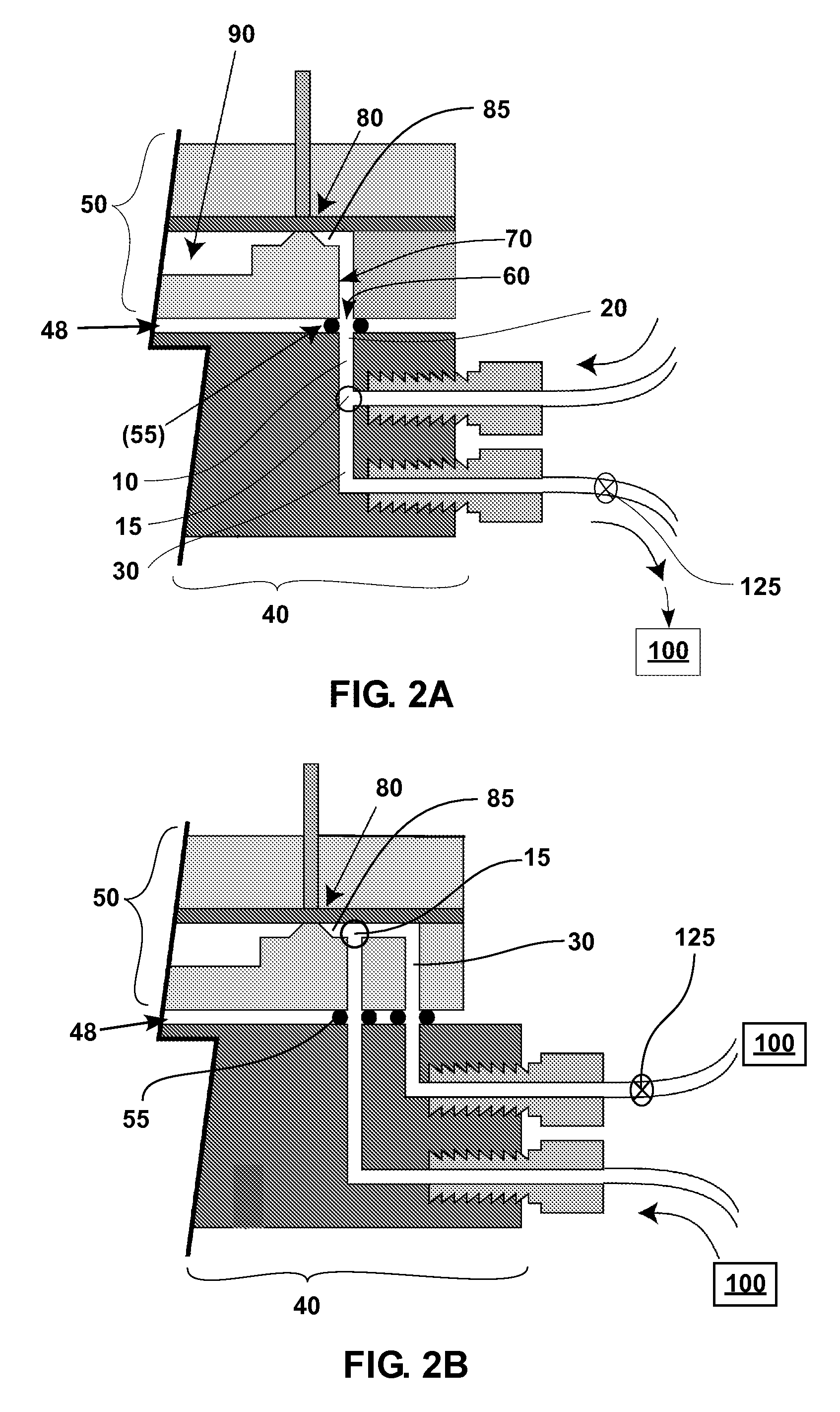
[0027]An adapter device for interfacing a microfluidic chip system with an external fluidic system according to the present disclosure, comprises an adapter between components of the external fluidic system and the microfluidic chip system. The adapter seals to the microfluidic chip to make fluid-tight connections between ports on the microfluidic chip and corresponding ports on the adapter. The adapter contains a number of internal “channels”. For each such channel, one of the two openings of the channel corresponds to a port on the microfluidic chip, while the other opening is configured to connect to the external fluidic system via tubing, threaded fittings, etc. Each adapter channel will carry fluids such as samples, reagents, wash solvents, or gases to the microfluidic chip (i.e. the inputs to the microfluidic process), and / or fluids such as synthesized product or waste from the microfluidic chip (i.e. the outputs of the microfluidic process). It should be appreciated that some...


PUM

PropertyMeasurementUnit
Forceaaaaaaaaaa
Volumeaaaaaaaaaa
Shapeaaaaaaaaaa

Abstract

An interface system and device for interfacing a microfluidic chip system is disclosed comprising an adapter having channels and ports connecting to the microfluidic chip system and an external fluidic system. An interface, device and method are provided herein, that disclose the connection of larger volumes of an external fluidic system to smaller volumes of a microfluidic chip system and the ability to effectively purge microfluidic channels without contamination.

Description

CROSS REFERENCE TO RELATED APPLICATIONS[0001]This application claims priority to U.S. Provisional Ser. No. 60 / 847,993 for “Methods and Devices for Interfacing with a Microfluidic Chip” filed on Sep. 28, 2006 all of which is incorporated herein by reference in its entirety.STATEMENT OF GOVERNMENT SUPPORT[0002]The present invention was made with support from the United States Government under Grant No. CA119347 awarded by the National Cancer Institute at Frederick. The United States Government has certain rights in the invention.BACKGROUND[0003]1. Field[0004]The present disclosure relates to the interfacing of an external system with a microfluidic device. In particular, an apparatus and method are disclosed wherein fluid from an external system is effectively provided to a microfluidic chip device by way of an adapter. More specifically, an interface system and method for interfacing with a microfluidic chip are disclosed.[0005]2. Description of Related Art[0006]Microfluidic systems ...

Claims


Application Information

Patent Timeline
IPC IPC(8): B01L11/00B29C65/00B32B38/00B01L99/00
CPCB01L3/502715B01L9/527B01L2200/025G01N2035/00158B01L2200/0689B01L2300/0816G01N35/1095B01L2200/027
Inventor VAN DAM, ROBERT MICHAELELIZAROV, ARKADIJHEATH, JAMES R.
Owner CALIFORNIA INST OF TECH
Learn More