
Fluid distribution and collection in landfills and contaminated sites

a technology for contaminated sites and landfills, applied in nuclear engineering, radioactive decontamination, portable shielded containers, etc., can solve the problems of increased leachate head on the liner, increased slope stability of landfills, and potential flooding of the gas collection system, so as to reduce differential settlement and related post-closure maintenance costs, the effect of increasing the quantity

Active Publication Date: 2008-06-05
BOARD OF TRUSTEES OPERATING MICHIGAN STATE UNIV
View PDF2 Cites 0 Cited by
  • Summary
  • Abstract
  • Description
  • Claims
  • Application Information

AI Technical Summary

Benefits of technology

The system achieves uniform leachate distribution, reduces differential settlement, increases gas production, and lowers installation and maintenance costs by eliminating the need for excavation and using a single permeable layer instead of multiple trenches or wells.

Problems solved by technology

Risks and drawbacks of leachate recirculation include, a potential decrease in the slope stability of landfills, a potential increase in the leachate head on the liner, if leachate collection system is not designed to efficiently drain injected and recirculated leachate, potential flooding of the gas collection system, and possible leachate seepage from the landfill side slopes, if an adequate buffer distance is not maintained.
Climate dependency, odor problems, interference with daily operations, poor aesthetics, and potential runoff of applied leachate into storm water management system are the drawbacks of surface application techniques.
Vertical wells can interfere with landfill daily operations.
Disadvantages and limitations of vertical wells and horizontal trenches include odor problems during installation due to excavation of waste, high capital cost of construction; and non-uniform distribution of leachate due to the formation of “dry zones” or “dry pockets” where injected leachate cannot reach.
The dry zones can also lead to differential settlement of waste which can result in greater landfill cap maintenance costs.
In addition, the amount of leachate that can be recirculated by these methods may not be sufficient to get rid of all leachate typically produced by landfills located in humid regions.

Method used


Image

  • Fluid distribution and collection in landfills and contaminated sites
  • Fluid distribution and collection in landfills and contaminated sites
  • Fluid distribution and collection in landfills and contaminated sites

Examples


example 1

[0078]In Example 1, where the permeable layer 112 was constructed of recycled, crushed glass, the permeable layer 112 had a thickness of about 0.15 m (0.5 ft).

[0079]The crushed recycled glass had an average particle diameter, D50 of approximately 10 mm (0.394 inches). The permeable layer 112 had a hydraulic conductivity equal to 3×10⁻² m / s. The fluid injection and removal system was constructed by first leveling the waste surface. Next, a non-woven lower geotextiles fabric was laid on the waste surface. Below the lower geotextiles fabric, from top to bottom, was a layer of silty soil (loess) used as a daily soil cover having a thickness or depth of about 50 mm (2 inches), a layer of municipal solid waste having a thickness or depth of about 20 m (66 ft) and a leachate collection and lining system. A layer of crushed glass having a thickness or depth of about 0.15 m (0.49 ft) was placed on the geotextiles to form the permeable layer 112. An upper geotextiles fabric was then placed ab...

example 2

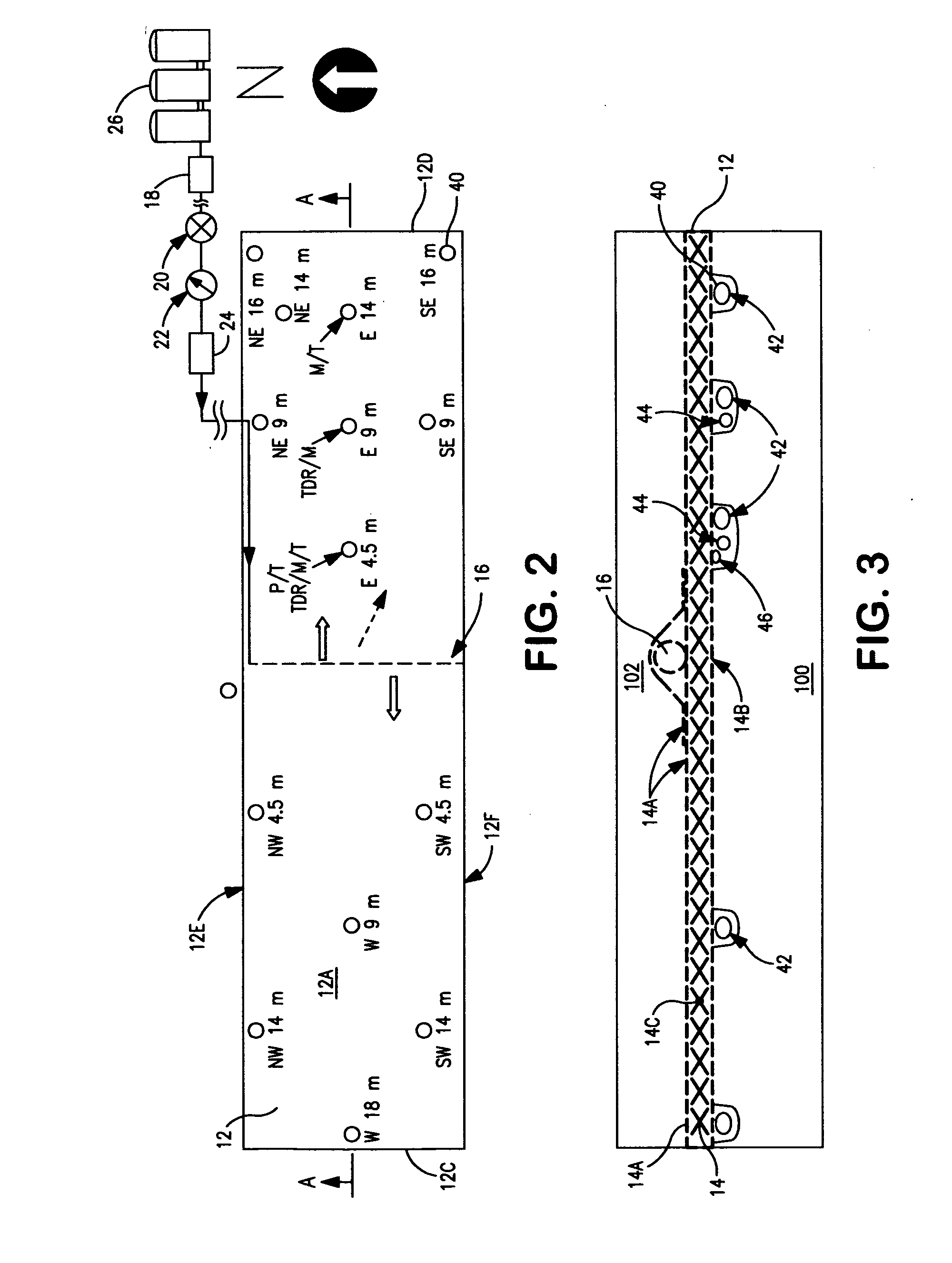
[0082]In Example 2, where the permeable layer 212 was constructed of shredded tires, the permeable layer 212 had an average thickness of about 0.5 m (1.6 ft). The perforated pipe was constructed of HDPE and was installed at the center of the permeable layer across the short side or width of the permeable layer and had a length of about 9 m (30 ft).

[0083]The data showing the response of impedance-based moisture sensors to the leachate injection in the shredded tires layer, showed that for a leachate injection rate of approximately 3.5 m3 / hr / m, the leachate traveled laterally in the shredded tires layer and reached the sensor located at approximately 15 ft (4.57 m) to the north of the injection pipe in about 2 to 3 minutes and reached the sensor located 23 to 27 m (75 to 90 ft) in about 20 to 25 minutes (FIG. 24). The data showed that for a leachate injection rate of 1.1 m3 / hr / m), leachate traveled laterally in the shredded tires layer and reached the sensors located at about 9 m (30 ...

example 3

[0084]In Example 3, the permeable layer 312 was a geocomposite drainage layer to be used to recirculate leachate. Table 1 sets forth the key properties of the components of the geocomposite drainage layer.

TABLE 1Physical Properties of the Geocomposite Drainage LayerUpperLowerComponentGeotextileGeotextileGeonetTypeNon-WovenWoven—Thickness (mm) (ASTM D 5199)20.55Mass per Unit Area (g / m2) (ASTM D270200—5261)Transmissivitya (cm2 / s) (ASTM D——204716-00)Permittivity (s−1) (ASTM D 4491)1.51.1—Hydraulic Conductivity (cm / s)0.30.05—(ASTM D 4491)Apparent Opening Size (mm)0.180.6~12.5(ASTM D 4751)Percent Open Area (%) (CW-02215)—1180Note:agradient of 0.1, normal load of 480 kPa, water (permanent) at 20° C., between steel plates for 15 minutes.

[0085]Before placing the geocomposite drainage layer, the surface of the landfill cell was essentially leveled. A topographic survey of the geocomposite drainage layer conducted after the placement of the geocomposite drainage layer indicated that the groun...


PUM


Abstract

A fluid injection and removal system to inject or remove fluids from a landfill or contaminated area. The system allows for treatment of waste in the landfill or the contaminated area. The fluid injection and removal system includes a permeable layer and at least one perforated pipe. The permeable layer enables essentially uniform distribution of the fluid into the underlying waste or contaminated area. The fluid injection and removal system can be combined with a leachate collection system to create a leachate recirculation system for use in a landfill. The leachate collection system includes at least one perforated collection pipe embedded in a drainage layer. Sensors can be provided in the permeable layer to enable the change in the physical characteristics of the waste adjacent the permeable layer to be monitored.

Description

CROSS-REFERENCE TO RELATED APPLICATIONS[0001]This application claims priority to Provisional Application Ser. No. 60 / 599,623, filed Aug. 6, 2004STATEMENT REGARDING FEDERALLY SPONSORED RESEARCH OR DEVELOPMENT[0002]Not ApplicableSTATEMENT REGARDING GOVERNMENT RIGHTS[0003]Not ApplicableBACKGROUND OF THE INVENTION[0004]1. Field of the Invention[0005]The present invention relates to fluid distribution and optionally collection in solid waste in landfills; and particularly bioreactive landfills and contaminated sites. In one aspect, the present invention relates to waste treatment liquid collection and recirculation in solid waste in landfills. In another aspect, the present invention relates to remediation of contaminants in the contaminated liquid or contaminated subsurface. In both instances, layer of a permeable, hydraulically conductive material is provided to allow the distribution of the fluids into the layer and from the layer into the landfill or contaminated site. The invention ...

Claims


Application Information

Patent Timeline
Patent Type & Authority Applications(United States)
IPC IPC(8): B09B5/00
CPCB09B1/00B09C1/02B09B3/00
Inventor KHIRE, MILIND V.
Owner BOARD OF TRUSTEES OPERATING MICHIGAN STATE UNIV
Learn More