
Degradable garbage security landfill device

A garbage and safety technology, which is applied in the field of degradable garbage safety landfill devices, can solve the problem that the integrated operation of turning soil, blanking and covering soil cannot be realized, increasing labor intensity and equipment purchase cost, and reducing landfill efficiency. and other problems, to achieve the effect of improving the efficiency of landfill work, reducing labor intensity and convenient operation.

Inactive Publication Date: 2018-07-31
陈才兴
View PDF0 Cites 0 Cited by
  • Summary
  • Abstract
  • Description
  • Claims
  • Application Information

AI Technical Summary

Problems solved by technology

[0002] In the process of processing some degradable waste, it is often necessary to carry out landfill operations. However, the traditional landfill device has limited functions and cannot realize the integrated operation of turning soil, blanking and covering soil, which seriously reduces the efficiency of landfill waste. At the same time It also increases the labor intensity and the cost of equipment purchase, which has major disadvantages and needs to be improved

Method used


Image

  • Degradable garbage security landfill device
  • Degradable garbage security landfill device
  • Degradable garbage security landfill device

Examples


Embodiment Construction

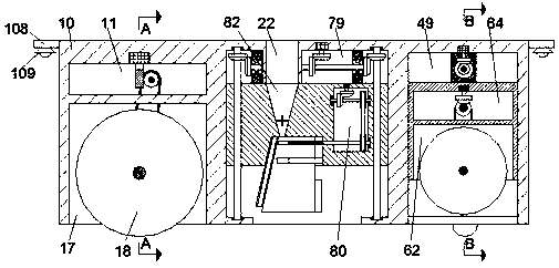
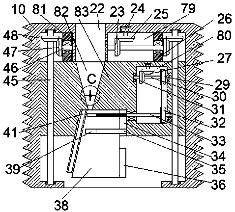
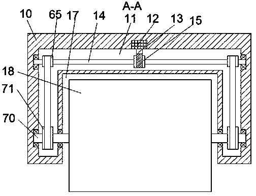
[0021] Such as Figure 1-Figure 5As shown, a safe landfill device for degradable garbage of the present invention includes a vehicle body 10 and a first inner cavity 11 arranged in the vehicle body 10, and a first inner cavity 11 is provided on the top inner wall of the first inner cavity 11. An electric rotating machine 12, the bottom end of the first electric rotating machine 12 is power-connected with a downwardly extending first worm 13, and the first worm 13 is power-connected with a turbine 15 located on the right side of the first worm 13, The turbine 15 is fixedly connected with a first transfer shaft 14 extending front and rear, and the front and rear extension ends of the first transfer shaft 14 are connected in rotation with the front and rear inner walls of the first inner chamber 11. The connecting shaft 14 is fixedly connected with the front and rear equal first transmission wheels 65, and the vehicle body 10 is provided with an installation chamber 17 located be...


PUM


Abstract

The invention discloses a degradable garbage security landfill device. The degradable garbage security landfill device comprises a vehicle main body and a first inner cavity formed in the vehicle mainbody; a first electric rotating machine is arranged in the inner wall of the top of the first inner cavity; the end tail of the bottom of the first electric rotating machine is in power connection with a first worm elongating downwards; the first worm is in power connection with a turbine located at the right of the first worm; the turbine is fixedly connected with a first changeover shaft elongating forwards and backwards; the front elongating end tail of the first changeover shaft is connected with the front inner wall of the first inner cavity in a rotation fitting manner; the rear elongating end tail of the first changeover shaft is connected with the rear inner wall of the first inner cavity in a rotation fitting manner; the first changeover shaft is fixedly connected first conveyingwheels which are opposite forwards and backwards; a security socket cavity located below the first inner cavity is formed in the vehicle main body; a second changeover shaft elongating forwards and backwards is arranged in the security socket cavity; the front end tail of the second changeover shaft penetrates through the front inner wall of the security socket cavity; the rear end tail of the second changeover shaft penetrates through the rear inner wall of the security socket cavity; the front end tail and the rear end tail of the second changeover shaft extend into the first inner cavity;the second changeover shaft is provided with second conveying wheels located in the first inner cavity; and the second conveying wheels are in power connection with the first conveying wheels throughconveying belts.

Description

technical field [0001] The invention relates to the technical field of garbage treatment, in particular to a safe landfill device for degradable garbage. Background technique [0002] In the process of processing some degradable waste, it is often necessary to carry out landfill operations. However, the traditional landfill device has limited functions and cannot realize the integrated operation of turning soil, blanking and covering soil, which seriously reduces the efficiency of landfill waste. At the same time It also increases labor intensity and equipment purchase cost, and has relatively large disadvantages that need to be improved. Contents of the invention [0003] The technical problem to be solved by the present invention is to provide a safe landfill device for degradable garbage, which can solve the above-mentioned problems in the prior art. [0004] The present invention is achieved through the following technical solutions: a safe landfill device for degrada...

Claims


Application Information

Patent Timeline
Patent Type & Authority Applications(China)
IPC IPC(8): B09B1/00
CPCB09B1/004
Inventor 陈才兴周守丽
Owner 陈才兴
Learn More