
Lighting device and lighting method

a technology of light source and light source, which is applied in the direction of lighting and heating apparatus, instruments, optical elements, etc., can solve the problems of system loss of energy, self-absorption, and reduce and achieve the effect of reducing performance (intensity) and efficiency

Active Publication Date: 2008-06-05
CREELED INC
View PDF48 Cites 91 Cited by
  • Summary
  • Abstract
  • Description
  • Claims
  • Application Information

AI Technical Summary

Benefits of technology

[0032]Furthermore, if the lumiphor is too thick, and / or if the luminescent material content in the lumiphor is too great, “self-absorption” may occur. Self-absorption occurs when light emissions within the packaging layer stay within the packaging layer to excite other luminescent material particles and eventually are absorbed or are otherwise prevented from exiting the device, thus reducing performance (intensity) and efficiency. Additionally, if the particle size of the luminescent material is too large, the particles of luminescent material can cause unwanted scattering of both light from the excitation source (e.g., the LED chip) and the light generated by the lumiphor.

Problems solved by technology

Back-scattered light which is scattered back into the solid state light emitter (e.g., light emitting diode chip) itself has a very low probability of coming out of the solid state light emitter, and hence, such back-scattering results in a system loss of energy.
Furthermore, if the lumiphor is too thick, and / or if the luminescent material content in the lumiphor is too great, “self-absorption” may occur.
Self-absorption occurs when light emissions within the packaging layer stay within the packaging layer to excite other luminescent material particles and eventually are absorbed or are otherwise prevented from exiting the device, thus reducing performance (intensity) and efficiency.
Additionally, if the particle size of the luminescent material is too large, the particles of luminescent material can cause unwanted scattering of both light from the excitation source (e.g., the LED chip) and the light generated by the lumiphor.

Method used


Image

  • Lighting device and lighting method
  • Lighting device and lighting method
  • Lighting device and lighting method

Examples


Embodiment Construction

)

[0063]The present inventive subject matter now will be described more fully hereinafter with reference to the accompanying drawings, in which embodiments of the inventive subject matter are shown. However, this inventive subject matter should not be construed as limited to the embodiments set forth herein. Rather, these embodiments are provided so that this disclosure will be thorough and complete, and will fully convey the scope of the inventive subject matter to those skilled in the art. Like numbers refer to like elements throughout. As used herein the term “and / or” includes any and all combinations of one or more of the associated listed items.

[0064]The terminology used herein is for the purpose of describing particular embodiments only and is not intended to be limiting of the inventive subject matter. As used herein, the singular forms “a”, “an” and “the” are intended to include the plural forms as well, unless the context clearly indicates otherwise. It will be further under...


PUM


Abstract

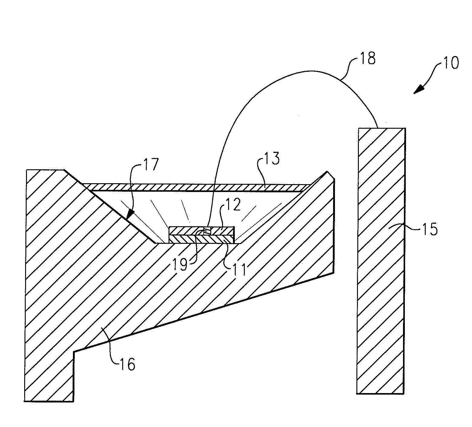
A lighting device, comprising a solid state light emitter and a light filter. At least a portion of light emitted by the light emitter contacts the filter, and at least part of the light passes through the filter. Also, such lighting devices further comprising lumiphor, in which at least some of the first part of the light is absorbed by the lumiphor, which then emits light, and at least a portion of any light emitted by the lumiphor directed toward the filter is reflected by the filter. Also, a method of lighting, comprising illuminating a solid state light emitter in such devices. Also, a lighting device, comprising a solid state light emitter; a lumiphor and filter means for allowing at least a portion of light emitted by the light emitter to pass through and for reflecting a second portion of light emitted by the lumiphor after the lumiphor is excited.

Description

CROSS-REFERENCE TO RELATED APPLICATIONS[0001]This application claims the benefit of U.S. Provisional Patent Application No. 60 / 861,830, filed Nov. 30, 2006, the entirety of which is incorporated herein by reference.FIELD OF THE INVENTION(S)[0002]The present inventive subject matter relates to a lighting device, in particular, a device which includes one or more solid state light emitters. In some aspects, the present inventive subject matter relates to a lighting device which includes one or more light emitting diode chips and one or more luminescent materials. The present inventive subject matter is also directed to lighting methods.BACKGROUND OF THE INVENTION(S)[0003]A large proportion (some estimates are as high as twenty-five percent) of the electricity generated in the United States each year goes to lighting. Accordingly, there is an ongoing need to provide lighting which is more energy-efficient. It is well-known that incandescent light bulbs are very energy-inefficient light...

Claims


Application Information

Patent Timeline
IPC IPC(8): F21V9/00F21V9/16F21K99/00H01L33/44H01L33/50
CPCH01L33/44H01L33/507Y10S362/80H01L2924/13091H01L2224/48091H01L2224/48247H01L2924/00014H01L2924/00
Inventor NEGLEY, GERALD H.VAN DE VEN, ANTONY PAULPICKARD, PAUL KENNETH
Owner CREELED INC
Learn More