
Crossover-Free Fiber Optic Coil Sensor and Winding Method

a fiber optic coil sensor and coil technology, applied in the field of fiber optics, can solve the problems of reducing the performance of the fiber optic gyroscope, the use of relatively expensive polarization-maintenance, and the inability to detect cross-over sites or contact points, so as to reduce the time-varying thermal gradient and eliminate the effect of crossover sites or contact points

Active Publication Date: 2008-06-05
MORGAN RES CORP
View PDF2 Cites 23 Cited by
  • Summary
  • Abstract
  • Description
  • Claims
  • Application Information

AI Technical Summary

Benefits of technology

[0017]It is a further object of the present invention to provide a radially-wound fiber optic coil and method for winding a fiber optic coil that substantially eliminates crossover sites or contact points between the optical fibers.
[0019]It is yet another object of the present invention to provide a wound fiber optic coil and winding method which reduces time-varying thermal gradients.

Problems solved by technology

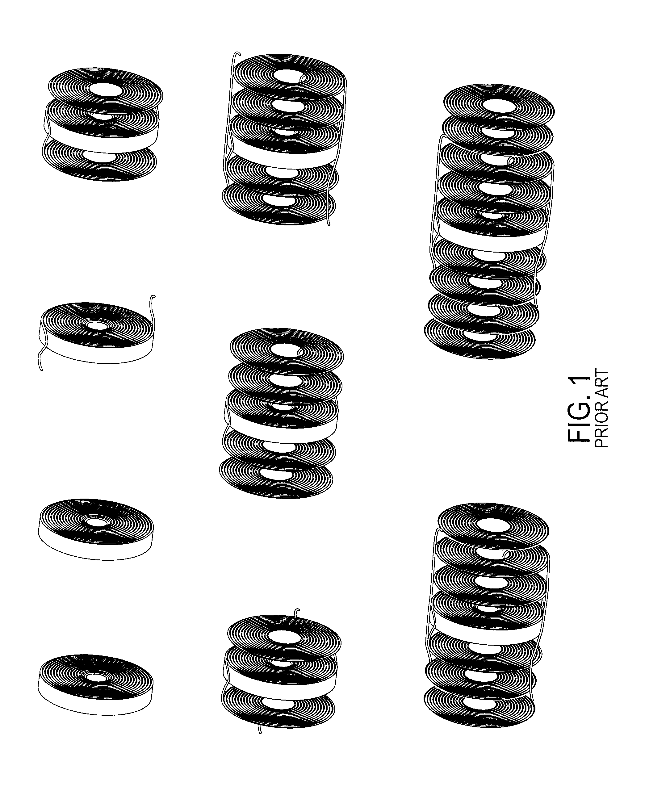
These crossover sites have been found to cause random polarization cross-coupling in the single mode fiber coil that substantially degrades the fiber optic gyroscope technology performance, causing polarization non-reciprocal (“PNR”) bias errors in the depolarized FOGs.
In the past, navigation-grade performance FOG designs have required the use of relatively expensive polarization-maintaining (“PM”) fibers.
Due to the significant cost advantage of SM fibers, depolarized interferometric FOGs have great cost-lowering potential.
Another problem with conventional FOGs is the presence of time-varying thermal gradients, which are a large source of FOG error.
Time-varying thermal gradients result in a phenomenon known as the Shupe effect, a phase shift due to time varying temperatures experienced by different segments of the coil, and resulting in increased bias.
Reducing varying thermal gradients requires complex, costly and time-consuming winding patterns that ensure that the phase shifts are symmetrical and do not result in bias.
These types of winding patterns have not been compatible with automatic, high-speed winding systems.
One disadvantage of the winding method disclosed in the '301 patent is that subsequent layer of coils after the first layers on either side of the coil form are laid directly on top of the preceding layers, a practice that could result in slumps and sags of the optical fiber.
Further, errors in the winding pattern are rapidly compounded as layer count increases, as each previous layer directly affects the positioning of the subsequent layer.
Spooling the fiber through the center hole is not practical from a manufacturing standpoint when using an automated winding configuration, and cutting a passage in the coil form compromises the structural stability and symmetry of the coil form.

Method used


Image

  • Crossover-Free Fiber Optic Coil Sensor and Winding Method
  • Crossover-Free Fiber Optic Coil Sensor and Winding Method
  • Crossover-Free Fiber Optic Coil Sensor and Winding Method

Examples


Embodiment Construction

[0040]Reference will now be made in detail to embodiments of the disclosed crossover-free fiber optical coil sensor and winding method, examples of which are illustrated in the accompanying drawings.

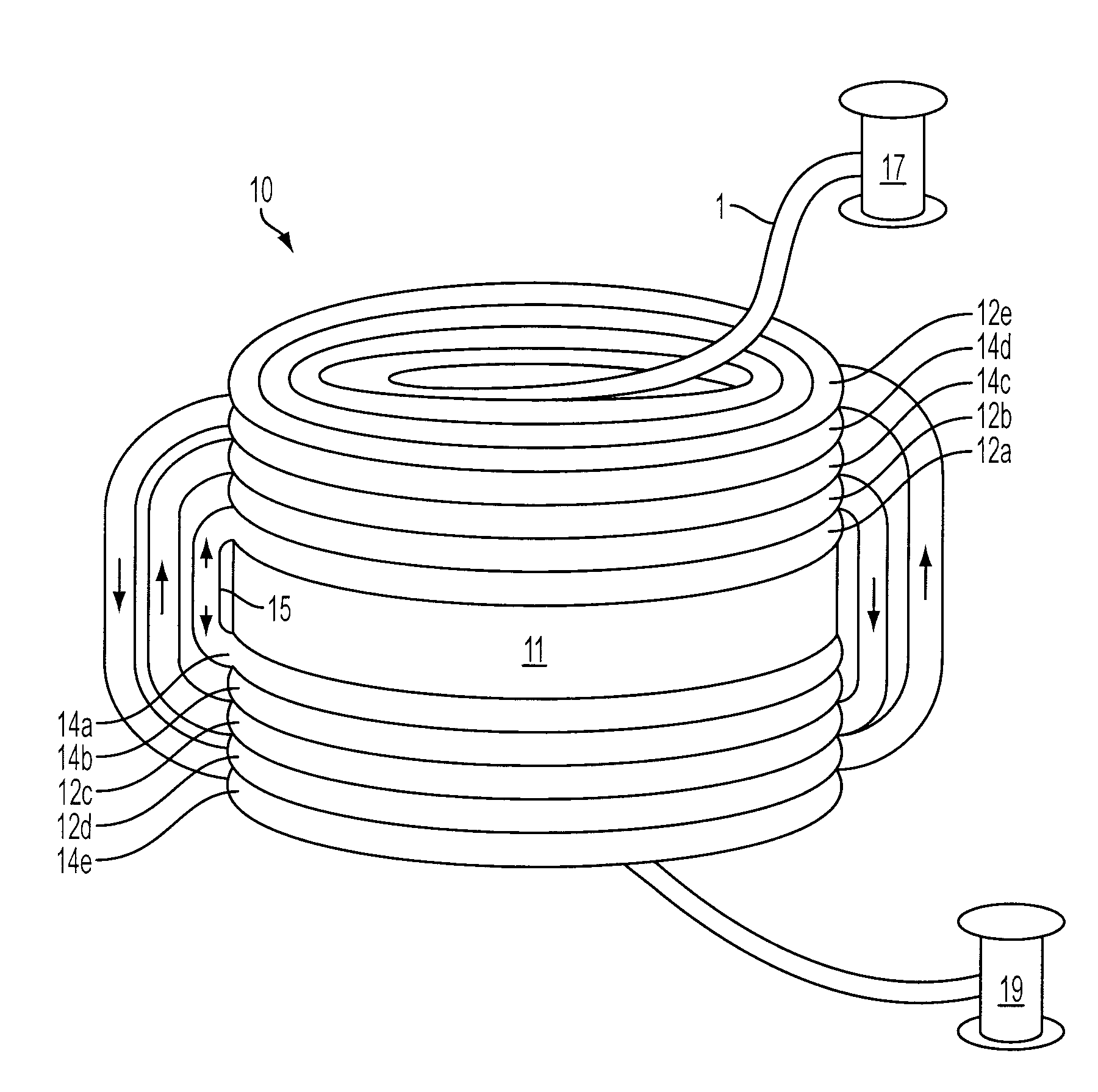
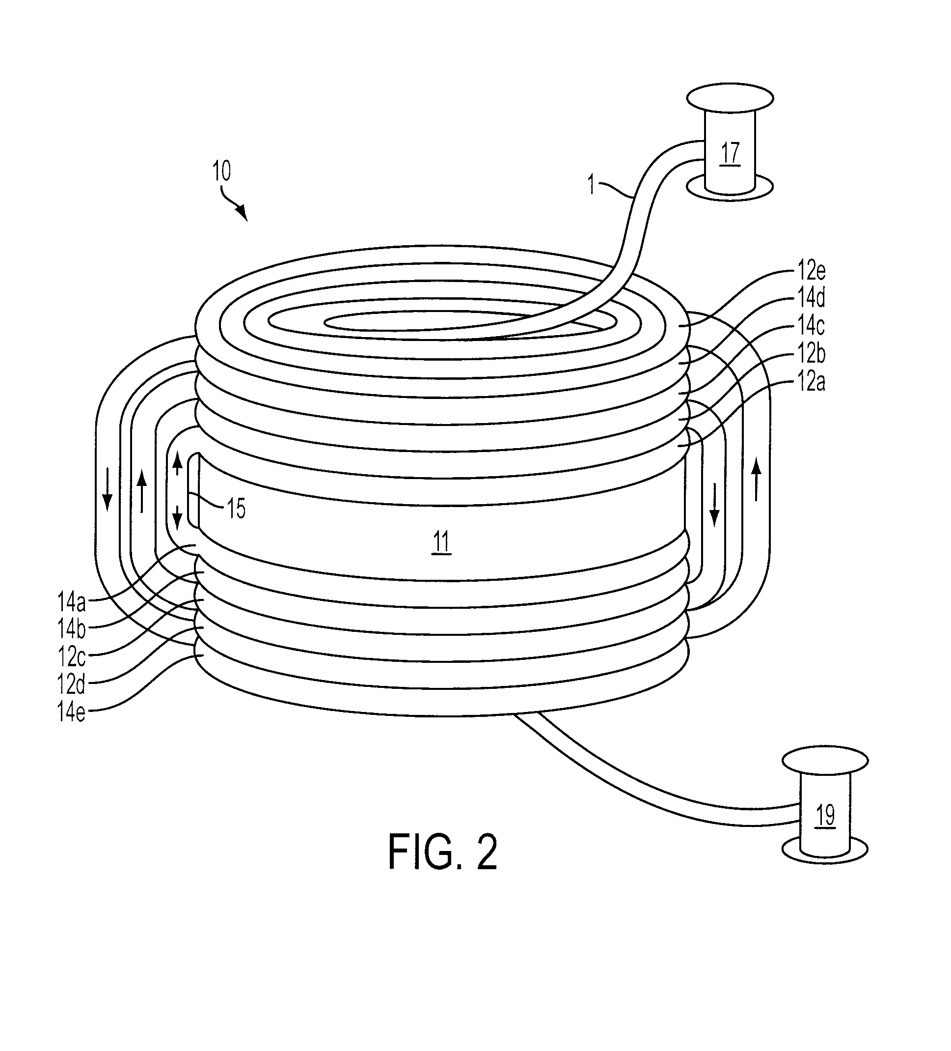
[0041]FIG. 2 is a diagram illustrating various embodiments of the invention wherein a coil form 11 (similar to a flat ring washer) provides structural support for a fiber optic coil 10. The fiber optic coil 10 comprises a plurality of coil layers, 12a through 12e and 14a through 14e formed from fiber optic cable 1 supplied from a first supply spool 17 and a second supply spool 19, respectively.

[0042]In some embodiments, winding of the fiber optic coil 10, is initiated by winding fiber optic cable onto a first supply spool 17 and a second supply spool 19. In a preferred embodiment, the amount of fiber optic cable wound onto the first supply spool 17 and the amount of fiber optic cable wound onto the second supply spool 19 are substantially equal in length. The amount of fiber optic cable ...


PUM

PropertyMeasurementUnit
diameteraaaaaaaaaa
thicknessaaaaaaaaaa
diameteraaaaaaaaaa

Abstract

A method for winding a crossover-free fiber optic coil sensor comprising: attaching a fiber optic cable to an outer edge of a coil form, wherein the coil form comprises a first side and a second side; forming a first outside-in coil layer on the first side of the coil form using a first winding head; attaching a first inside-out separator on top of the first outside-in coil layer; forming a first inside-out coil layer on top of the first inside-out separator using the first winding head; forming a second outside-in coil on the second side of the coil form using a second winding head; attaching a second inside-out separator on top of the second outside-in coil layer; and forming a second inside-out coil layer on top of the second inside-out separator using the second winding head.

Description

[0001]This application claims priority from Provisional U.S. Patent Application Ser. No. 60 / 796,014, filed Apr. 28, 2006, which is hereby incorporated by reference in its entirety.GOVERNMENT LICENSE RIGHTS[0002]This invention was made with Government support under contract number DAAH01-03-C-R203, awarded by the United States Department of Defense. The Government has certain rights in the invention.[0003]This application includes material which is subject to copyright protection. The copyright owner has no objection to the facsimile reproduction by anyone of the patent disclosure, as it appears in the Patent and Trademark Office files or records, but otherwise reserves all copyright rights whatsoever.FIELD OF THE INVENTION[0004]The instant disclosure relates to the field of fiber optics. More particularly, the present invention relates to the field of wound optical fibers and fiber optic sensors.BACKGROUND OF THE INVENTION[0005]Fiber optic gyroscopes (“FOGs”) utilize a coiled length...

Claims


Application Information

Patent Timeline
Patent Type & Authority Applications(United States)
IPC IPC(8): G01C19/72B65H75/18B29C65/56B29C65/48
CPCB65H54/10G02B6/4458B65H2701/32B65H55/04
Inventor WILLIAMS, MARTY R.
Owner MORGAN RES CORP
Learn More