Backlight control apparatus, dislay device, and method for controlling backlight of display device

a display device and control apparatus technology, applied in the direction of static indicating devices, pulse techniques, instruments, etc., can solve the problem of 1 inability to cope with a fluctuation of backligh

Inactive Publication Date: 2008-06-05
KK TOSHIBA
View PDF4 Cites 12 Cited by
  • Summary
  • Abstract
  • Description
  • Claims
  • Application Information

AI Technical Summary

Problems solved by technology

The conventional technique in Patent Document 1 cannot cope with a fluctuation of the backlight described below.

Method used


Image

  • Backlight control apparatus, dislay device, and method for controlling backlight of display device
  • Backlight control apparatus, dislay device, and method for controlling backlight of display device
  • Backlight control apparatus, dislay device, and method for controlling backlight of display device

Examples


Embodiment Construction

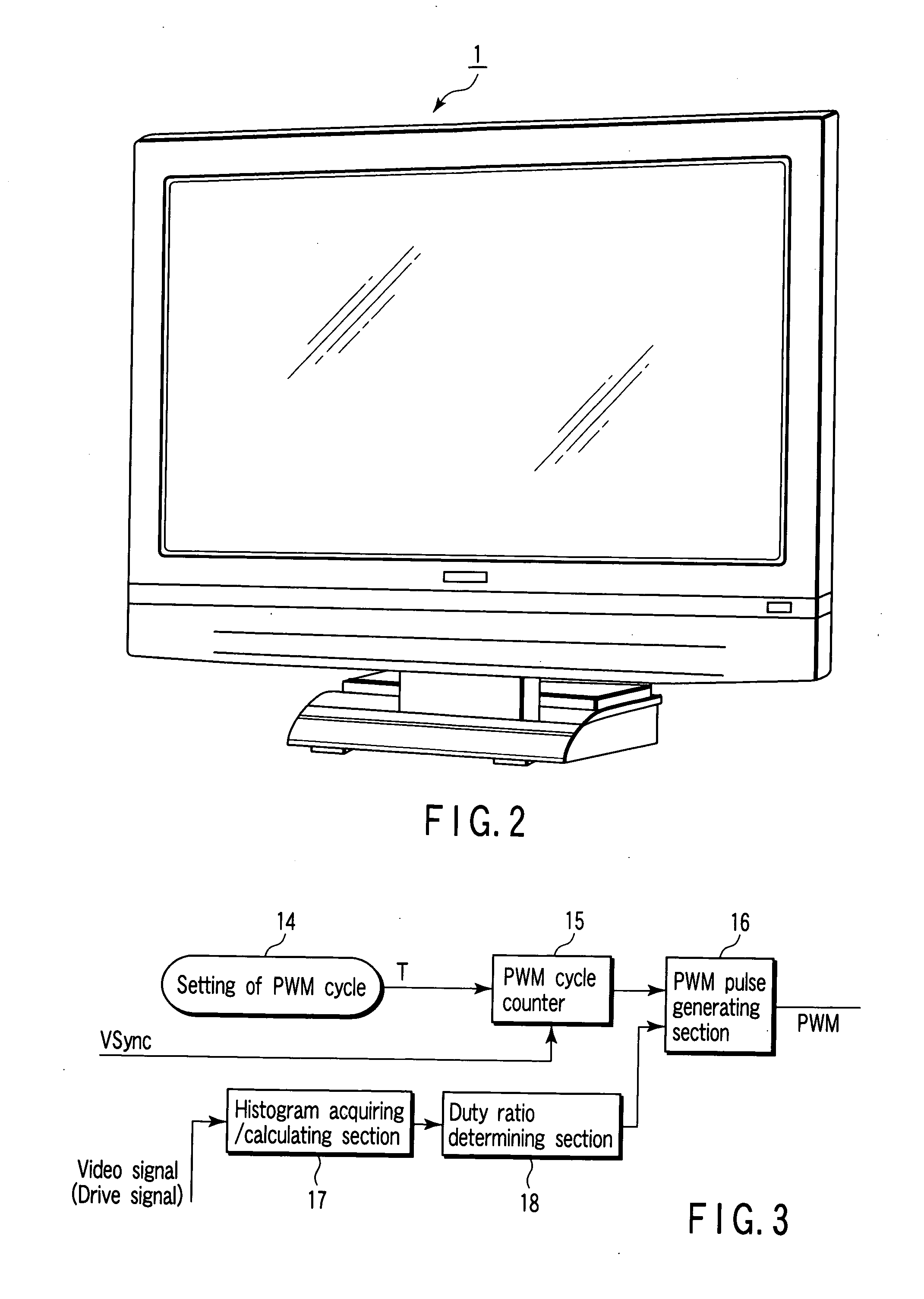
[0014]Various embodiments according to the invention will be described hereinafter with reference to the accompanying drawings. In general, according to one embodiment of the invention, a backlight control apparatus comprising: a setting section which sets a count value according to a cycle of a PWM pulse signal; a counter section which counts to the count value set by the setting section; a comparing / changing section which compares an actually measured count value of the counter section at a timing of a given vertical synchronous signal with a set count value set according to the cycle of the PWM pulse signal so as to change the count value according to the compared result; a determining section which generates a histogram of a given video signal so as to determine a duty ratio based on the histogram; and a PWM pulse signal generating section which generates a PWM pulse signal based on the counted result from the counter section and the duty ratio determined by the determining sect...


PUM


Abstract

According to one embodiment, a backlight control apparatus includes a setting section which sets a count value according to a cycle of a PWM pulse signal, a counter section which counts to the count value set by the setting section, a comparing/changing section which compares an actually measured count value of the counter section at a timing of a given vertical synchronous signal with a set count value set according to the cycle of the PWM pulse signal so as to change the count value according to the compared result, a determining section which generates a histogram of a given video signal so as to determine a duty ratio based on the histogram, and a PWM pulse signal generating section which generates a PWM pulse signal based on the counted result from the counter section and the duty ratio determined by the determining section.

Description

CROSS-REFERENCE TO RELATED APPLICATIONS[0001]This application is based upon and claims the benefit of priority from Japanese Patent Application No. 2006-324473, filed Nov. 30, 2006, the entire contents of which are incorporated herein by reference.BACKGROUND[0002]1. Field[0003]One embodiment of the invention relates to a backlight control apparatus for a backlight section of a flat panel display device, a display device, and a method for controlling a backlight of the display device.[0004]2. Description of the Related Art[0005]Recently, plane display devices such as liquid crystal display devices, EL displays and plasma displays have been widely developed and used. Liquid crystal display devices have a backlight section which irradiates back surfaces of display elements. The irradiation by means of the back light section is not always carried out with luminance of 100%, and thus the luminance of the irradiation is occasionally changed according to luminance of video signals.[0006]In...

Claims


Application Information

Patent Timeline
Patent Type & Authority Applications(United States)
IPC IPC(8): H03K23/00G09G3/34
CPCG09G3/3406G09G2310/08G09G2320/0247H05B41/3927G09G2360/16H03K7/08G09G2320/064
Inventor HONDA, YUICHI
Owner KK TOSHIBA
Why Eureka
Try Eureka