
Current multiplexing circuit for optical power monitoring

Inactive Publication Date: 2008-06-05
JDS UNIPHASE CORP
View PDF1 Cites 11 Cited by
  • Summary
  • Abstract
  • Description
  • Claims
  • Application Information

AI Technical Summary

Benefits of technology

[0010]Another aspect of the present invention relates to a method for monitoring a plurality of current signals using the current multiplexing circuit of the present invention, the method comprising the steps of: a) providing the plurality of current signals to the plurality of input terminals, b) recording a reference signal obtained from an output of the operational amplifier when the multip

Problems solved by technology

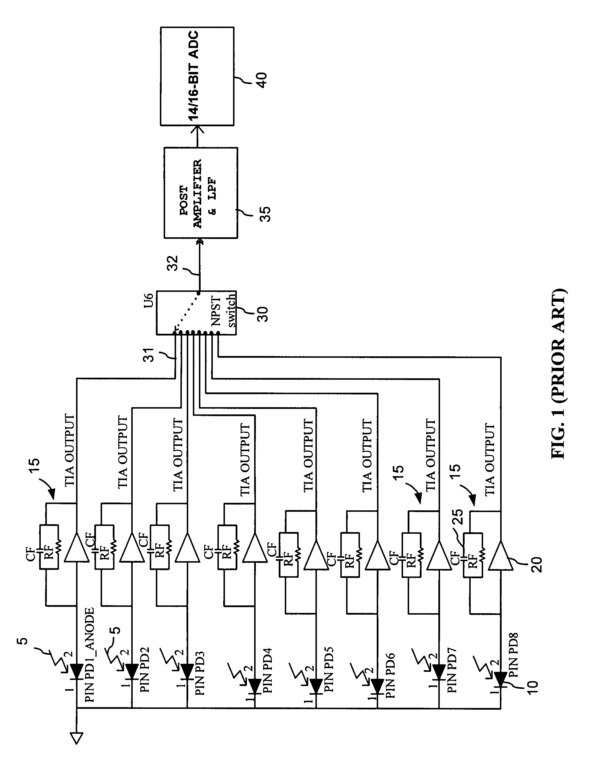
Furthermore, the material costs of the circuitry of FIG. 1 is high due the large number of TIAs, each requiring precision resistors RF for the trans-impedance (TZ) feedback circuits.
Since each of the TIAs 15 has to be powered, the resulting circuit consumes a relatively large amount of electrical power.

Method used


Image

  • Current multiplexing circuit for optical power monitoring
  • Current multiplexing circuit for optical power monitoring
  • Current multiplexing circuit for optical power monitoring

Examples


Embodiment Construction

[0025]The term “terminal” is used herein to mean a point of electrical connection, for example on a circuit board, including but not limited to leads, nodes, pins and other types of electrical connectors. A terminal used as an input or output of a device or a circuit board element is also referred to herein as “port”. The terms “current” and “potential” when used as nouns refer herein to electrical current and electrical potential, respectively.

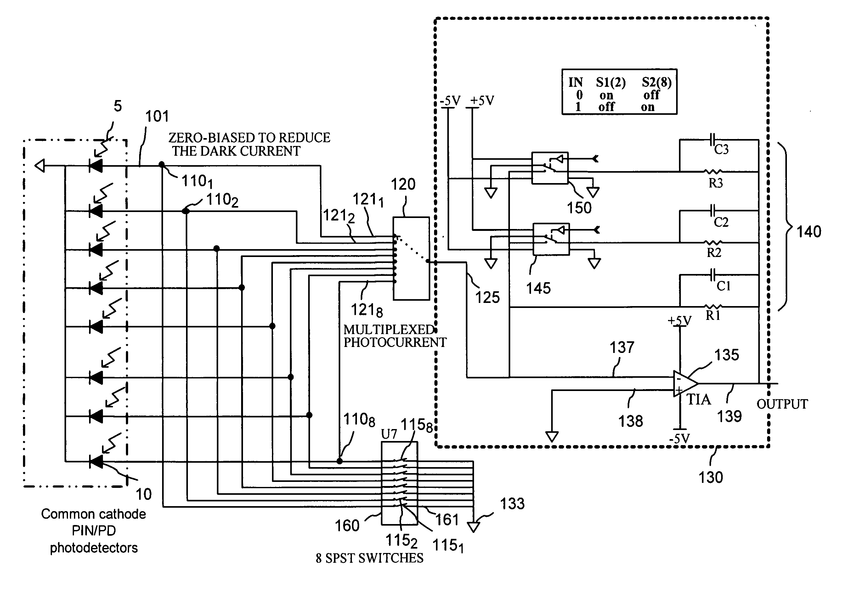
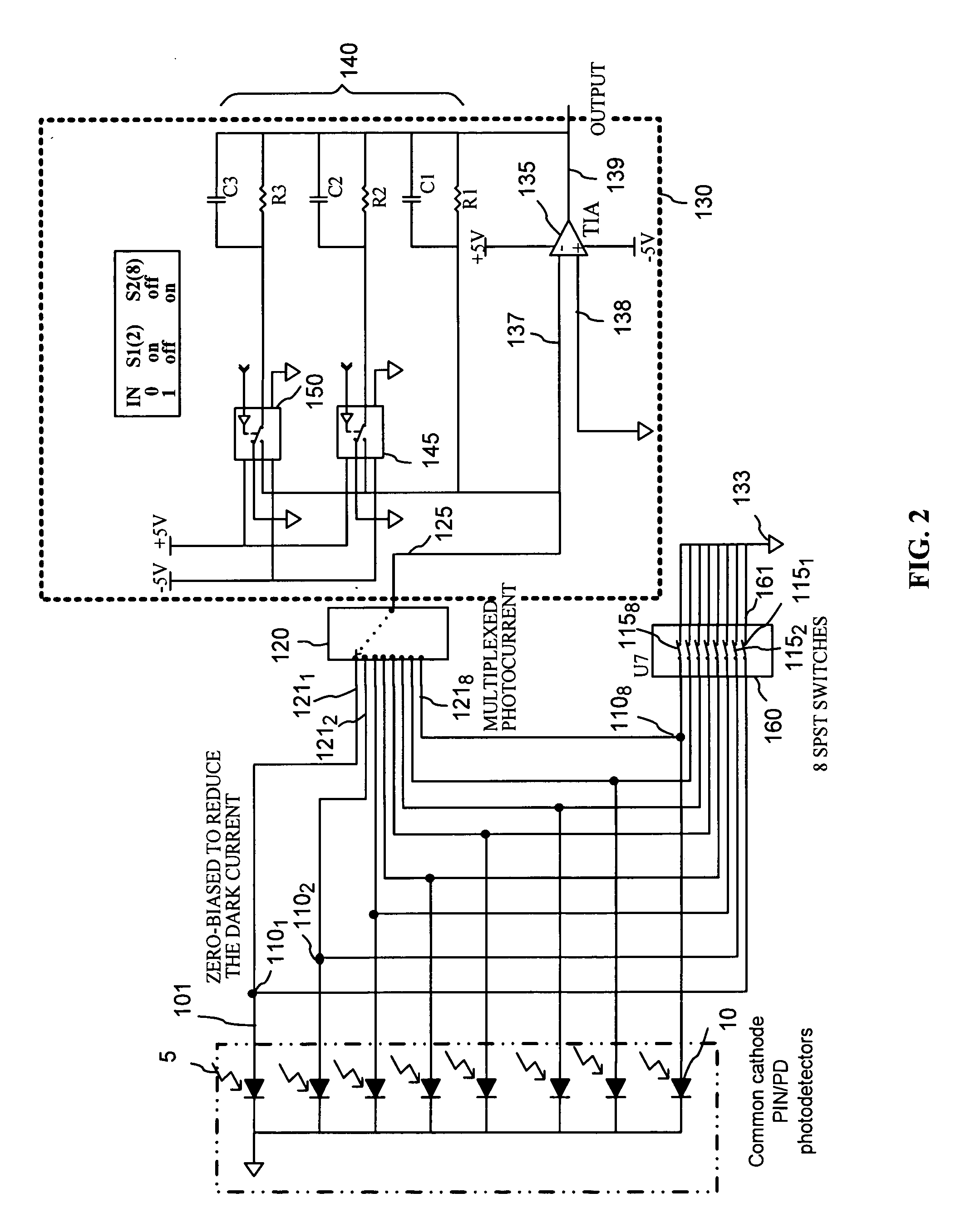
[0026]A preferred embodiment of a multiplexing circuit for multiplexing a plurality of current signals according to the present invention is shown in FIG. 2, wherein electrical connections between circuit elements are schematically shown by solid lines.

[0027]A plurality of input terminals 1101 . . . 110N, hereinafter generally referred to as input terminals 110, are provided for receiving a plurality of current signals in the form of electrical currents In, one current signal per input terminal, from a plurality of photodetectors (PD) 10, whi...


PUM


Abstract

The invention provides a current multiplexing circuit for time-domain multiplexing a plurality of current signals such as photocurrents that are received in a plurality of input terminals. The current signals are multiplexed using one or more analog low-resistance switches operational to connect each of the input terminals to an output switch terminal at a time in a selected sequence, while coupling the other input terminals and the output switch terminal to a reference potential such as ground. The current multiplexing circuit can be used in an optical power monitor with auto-calibration functionality for monitoring a plurality of optical signals.

Description

CROSS-REFERENCE TO RELATED APPLICATIONS[0001]The present invention claims priority from U.S. Provisional Patent Application No. 60 / 854,423 filed Oct. 26, 2006, entitled “Method of measuring multiplexed photocurrents using analog CMOS switch”, which is incorporated herein by reference for all purposes.TECHNICAL FIELD[0002]The present invention generally relates to a circuit and method for multiplexing electrical currents, and particularly relates to an optical power monitor utilizing direct photocurrent multiplexing for monitoring a plurality of optical signals.BACKGROUND OF THE INVENTION[0003]Optical communication systems often require monitoring of optical power in a plurality of optical channels. One example of optical systems where such multi-channel optical power monitors are typically called for are optical add-drop multiplexers (OADM) installed at optical network nodes. A typical OADM includes a plurality of optical taps for tapping optical power of de-multiplexed channels to ...

Claims


Application Information

Patent Timeline
IPC IPC(8): H03K17/00
CPCH03K17/005H04J3/047H03K17/78
Inventor IVANCEVIC, DUSANRAMAKRISHNAN, SRIKANTH
Owner JDS UNIPHASE CORP
Learn More