
Polymer-based composite structural underlayment board and flooring system

a technology of structural underlayment and polymer-based composites, which is applied in the direction of building repairs, transportation and packaging, synthetic resin layered products, etc., can solve the problems of the service life of the flooring system, and achieve the effects of good dimensional stability, easy handling, and light weigh

Active Publication Date: 2008-05-29
JOHNS MANVILLE CORP
View PDF30 Cites 19 Cited by
  • Summary
  • Abstract
  • Description
  • Claims
  • Application Information

AI Technical Summary

Benefits of technology

The improved building flooring system described in this patent provides a solution for current flooring systems by using a layer of polymer-based composite structural underlayment boards. These boards have good strength, durability, and can easily be cut and formed on the job site. They also have good thermal and acoustical properties, are resistant to moisture and fungal growth, and can bond securely to a nonstructural finish-flooring layer. The underlayment layer is made up of multiple layers of these boards, which are secured to the building subfloor and form a strong and stable foundation for the finish-flooring layer. The facer on the top of each board provides a good surface for bonding the finish-flooring layer and is resistant to degradation from alkali. Overall, this system provides a better solution for building flooring.

Problems solved by technology

While these underlayment boards perform satisfactorily, the physical properties of these underlayment boards, such as but not limited to their weight, handleablity, cutablity, durability, flame spread rating, water absorption and / or fungus growth characteristics, etc. can present problems during the installation of the underlayment layer and over the anticipated service life of a flooring system.

Method used


Image

  • Polymer-based composite structural underlayment board and flooring system
  • Polymer-based composite structural underlayment board and flooring system
  • Polymer-based composite structural underlayment board and flooring system

Examples


Embodiment Construction

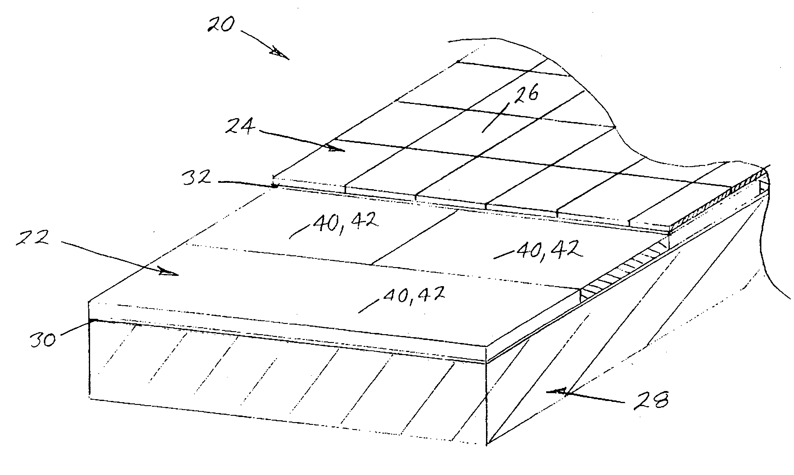
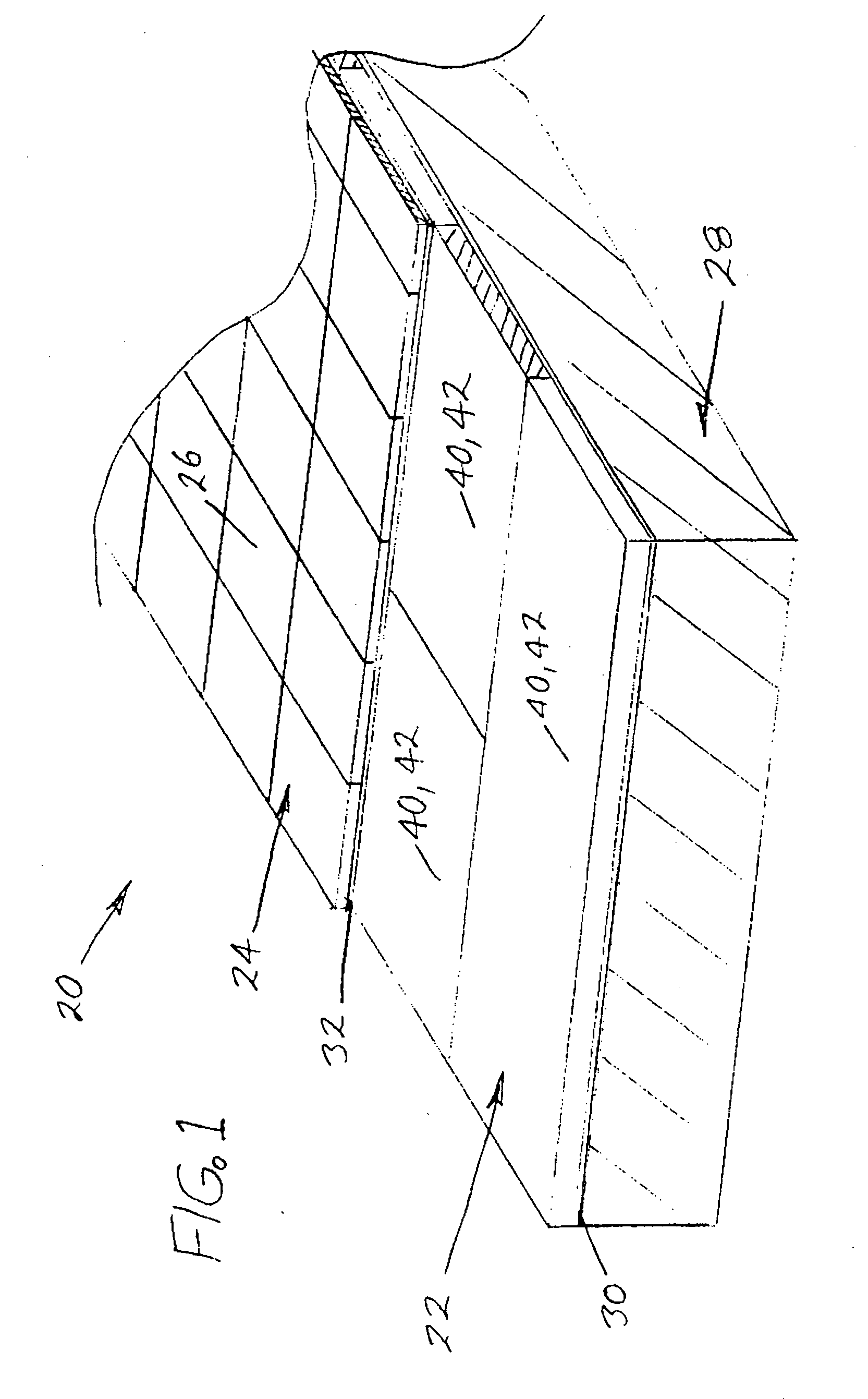
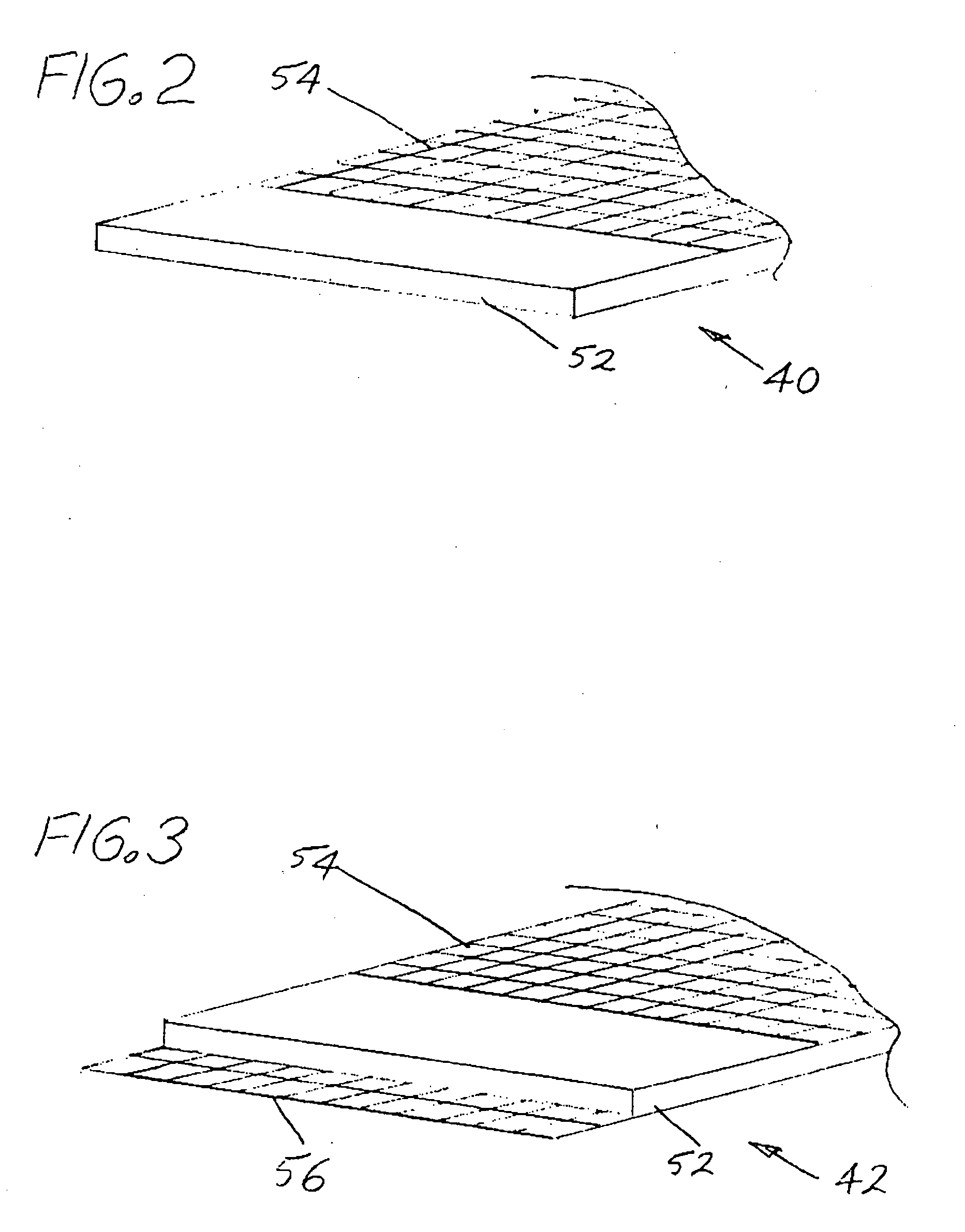
[0008]As schematically shown in FIG. 1, the flooring system 20 of the subject invention includes an underlayment layer 22 formed by a plurality of the polymer-based composite structural underlayment boards 40 or 42 of FIGS. 2 and 3 and a nonstructural finish-flooring layer 24. While the nonstructural finish-flooring layer 24 may be made of other nonstructural finish-flooring materials such as: thin, flat or substantially flat, manmade or natural, hard, rigid stone slabs (e.g. marble slabs and flagstones such as sandstone and shale slabs), linoleum, or resilient tiles (e.g. vinyl tiles), as shown, the nonstructural finish-flooring layer 24 is formed by a plurality of hard, rigid tiles 26 (e.g. 8×8 inch or 12×12 inch ceramic tiles). The underlayment layer 22 is normally coextensive with or substantially coextensive with an upper surface of a building subfloor structure 28, such as but not limited to a concrete floor slab. The polymer-based composite structural underlayment boards 40 o...


PUM

PropertyMeasurementUnit
densityaaaaaaaaaa
densityaaaaaaaaaa
thicknessaaaaaaaaaa

Abstract

A building flooring system includes a plurality of polymer-based composite structural underlayment boards overlaying and secured to a building subfloor to form an underlayment layer over the building subfloor and a nonstructural finish-flooring layer overlaying and bonded to the underlayment layer. The polymer-based composite structural underlayment boards each have a polymer material core layer or a predominantly polymer material core layer that typically contains from 1% to 40% by weight filler(s) and a density between 1.6 lbs / ft3 and 25 lbs / ft3. At least the top or bottom major surface of each of the polymer-based composite structural underlayment boards is overlaid by a facer that reinforces and strengthens the polymer-based composite structural underlayment board and that is generally coextensive with and bonded to the overlaid major surface of the polymer-based composite structural underlayment board.

Description

BACKGROUND OF THE INVENTION[0001]The subject invention relates to building flooring systems and in particular to a polymer-based composite structural underlayment board and an improved building flooring system that includes a plurality of the polymer-based composite structural underlayment boards overlaying and secured to a building subfloor to form an improved underlayment layer over the building subfloor and a nonstructural finish-flooring layer overlaying and bonded to the underlayment layer. As used in this specification and claims, a “nonstructural finish-flooring layer” is a flooring layer formed of: hard, rigid tiles (e.g. ceramic tiles); thin, flat or substantially flat manmade or natural hard rigid stone slabs (e.g. marble slabs and flagstones such as sandstone and shale slabs); linoleum; and resilient tiles (e.g. vinyl tiles).[0002]In current building flooring systems, the nonstructural finish-flooring layers of the systems may be bonded directly to the upper surfaces of t...

Claims


Application Information

Patent Timeline
Patent Type & Authority Applications(United States)
IPC IPC(8): B32B7/02
CPCB32B5/18B32B27/12Y10T428/2495Y10T428/24992E04F15/02E04G23/0285Y10T428/249992Y10T428/249991Y10T428/249981
Inventor PARADIS, DUANE R.TIERNEY, PATRICK WILLIAM
Owner JOHNS MANVILLE CORP
Learn More