Testing device housing

a testing device and housing technology, applied in the field of housing for testing devices, can solve the problems of not being user-friendly, awkward to hold, and user's hand grip is generally limited to the device with her fingers, so as to facilitate the use of testing devices, increase thickness, and ensure the effect of grip

Inactive Publication Date: 2008-05-29
MCNEIL PPC INC
View PDF7 Cites 18 Cited by
  • Summary
  • Abstract
  • Description
  • Claims
  • Application Information

AI Technical Summary

Benefits of technology

[0013]Instead of substantially following the essentially elongated flat shape of the test strip therein, a testing device housing formed in accordance with the principles of the present invention may be formed to have an increased thickness such that the ratio of the thickness to the width is significantly greater than the thickness to width ratio of the testing strip housed therein. The thickness of the housing preferably is selected to provide a sufficient gripping area permitting stable gripping of the lateral sides (instead of the top and / or bottom surfaces) of the testing device housing extending along the thickness of the testing device housing. Such increased thickness permits stable gripping of the testing device housing in any orientation whereas prior art testing devices typically have a much smaller thickness (because the test strip generally has a thickness significantly smaller than its width) and thus permit stable gripping only along the top and bottom surfaces of the testing device housing.
[0014]Because the increased thickness of the testing device housing facilitates gripping of the lateral side surfaces of the testing device housing, in accordance with a further aspect of the present invention, surface texturing (e.g., ribs, grooves, roughening, raised or textured surface patterns, etc.) may be provided not only on the top and / or bottom surfaces but also on the lateral side surfaces of the testing device housing extending along the thickness of the housing. Such surface texturing further enhancing stable gripping of the testing device housing.
[0015]In accordance with another aspect of the present invention, a testing device housing may be formed to facilitate collection of a biological sample by a user performing a self-test while also reducing the likelihood of direct contact with the sample biological fluid during collection. In particular, the sample-collecting end of a testing device for self-testing often is provided at an extreme end of the testing device housing to reduce the likelihood of direct contact between the sample biological fluid to be collected and the hands and / or fingers of the user as the specimen is collected. For instance, the sample-collecting end of a pregnancy tester is generally provided at an extreme end of an elongated testing device housing long enough to permit gripping of the testing device housing far enough from the stream of urine during sample collection. In accordance with one aspect of the present invention, a testing device housing may be elongated to house an elongated test strip therein, and may further include an ergonomic gripping section at a proximal-most end opposite the distal specimen-collecting end. The ergonomic gripping section is distinguished by being angled with respect to the major longitudinal axis of the housing in a direction upward from the top surface of the testing device (generally defined as the surface in which a window for viewing test results is provided). In other words, the major plane of the ergonomic gripping section (i.e., the plane in which the top and bottom surfaces of the gripping section lie) is angled upwardly from the major plane of the testing device housing (i.e., the plane in which the top and bottom surfaces of the testing device housing lie) during use. Thus, if the sample collecting region is held in a urine stream, the gripping section is angled upward towards the user's hand and is easier to hold during sample collection. A finger depression may be provided on the top and / or bottom surfaces of the ergonomic gripping section to further facilitate gripping of the gripping section.

Problems solved by technology

Such dimensions when applied to an absorbent tip assure efficient and accurate sample collection without affecting testing by flooding, yet are not necessarily user-friendly when applied to a cap for covering such absorbent tip.
The user therefore is generally limited to gripping the device with her fingers in only one orientation—on the top and bottom surfaces.
Such a flat housing that may be awkward to hold in a stable position during specimen collection.
The awkwardness of such sample collection increases the desirability of a testing device housing shaped to minimize the chances of the user soiling her hands or fingers during sample collection and to maximize the ergonomics of sample collection.

Method used


Image

  • Testing device housing
  • Testing device housing
  • Testing device housing

Examples


Embodiment Construction

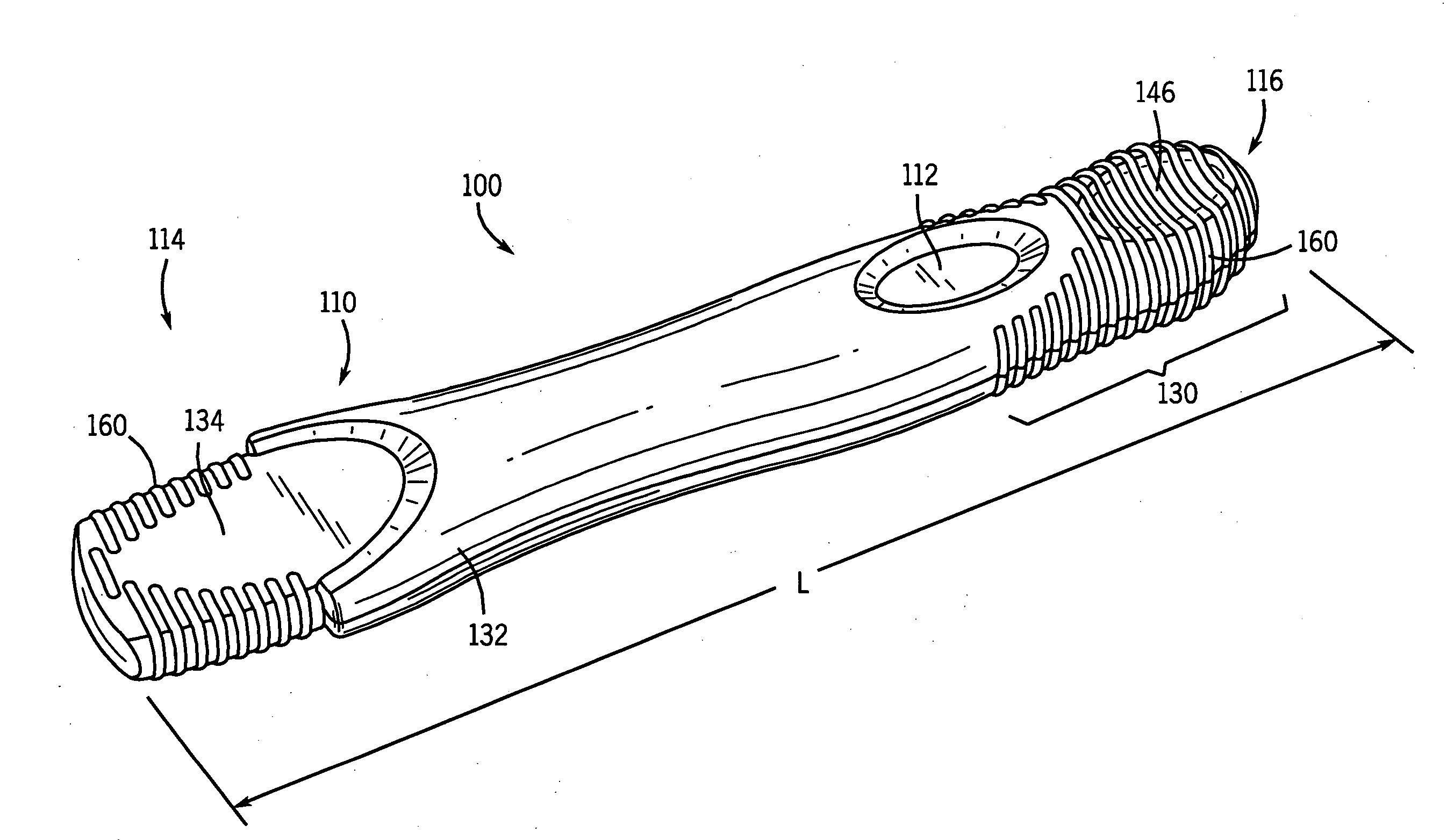
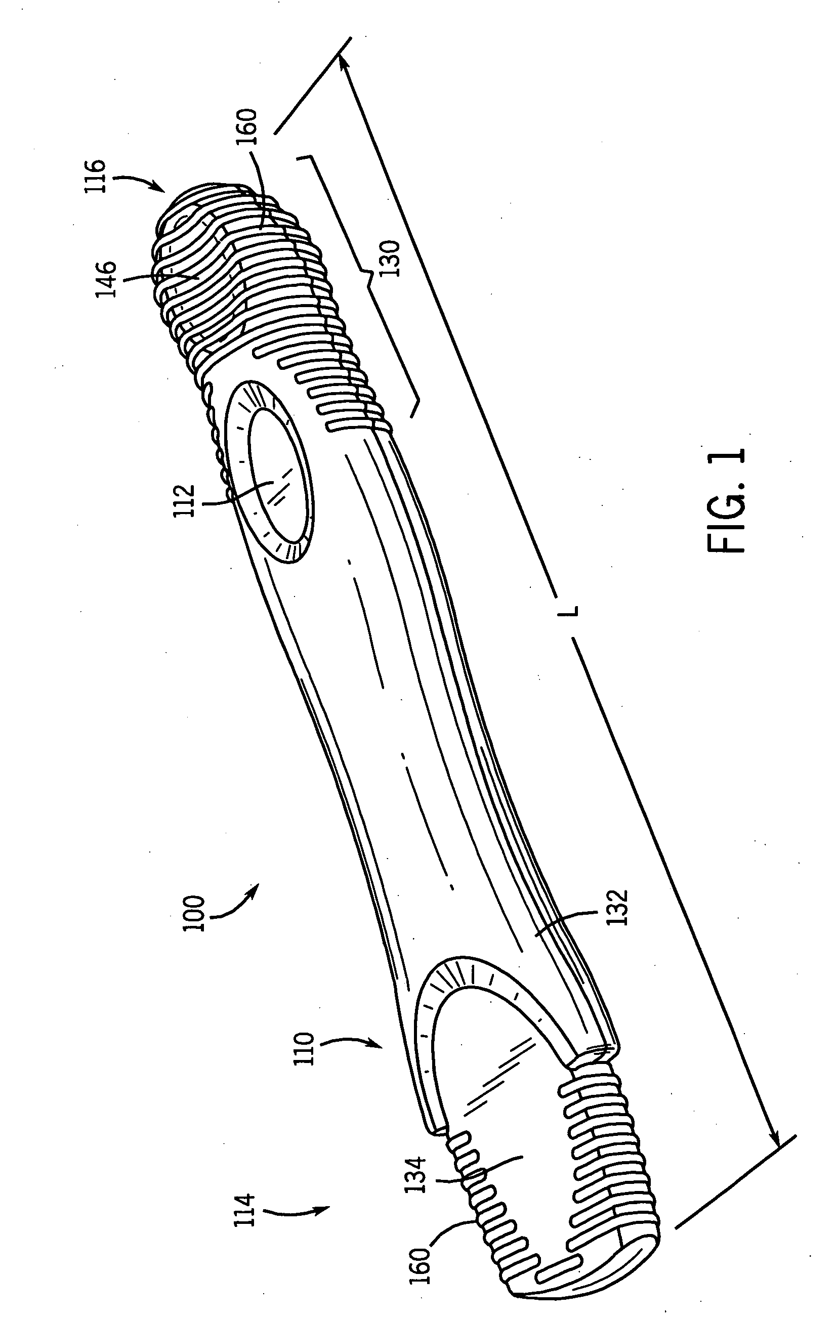
[0025]An exemplary portable testing device 100 formed in accordance with the principles of the present invention is illustrated in FIGS. 1-7. Testing device 100 has a generally elongated housing 110 for components for receiving and testing a biological sample or specimen (the terms specimen and sample are used interchangeably herein). Any of the various testing methods and devices known in the art may be used to determine the medical condition being tested. Such technology does not form a part of the claimed invention and thus is not described in detail. A window 112 may be formed in housing 110 to display results of the test to be performed by testing device 100. The position of window 112 along the length L of housing 110 (extending along the longitudinal axis of housing 110) may be determined based on a variety of factors, such as the required distance of the result region of the testing components within housing 110 from specimen-collecting end 114. In the exemplary housing of F...


PUM

PropertyMeasurementUnit
widthaaaaaaaaaa
thicknessaaaaaaaaaa
angleaaaaaaaaaa

Abstract

A housing for a testing device formed to facilitate ergonomic and / or easy and stable gripping, particularly during specimen-collection. The housing is particularly suitable for use in a self-testing device. Various features may be provided in accordance with the principles of the present invention to achieve the ergonomic and / or easy and stable gripping. For instance, the gripping end of the housing is angled so that a user may readily hold the testing device to collect a specimen without soiling herself. Additionally, or alternatively, the housing may be proportioned to have lateral side surfaces with sufficient surface area to permit gripping of the housing not only on the top and bottom surfaces (as in typical testing devices), but also on only the lateral side surfaces. Additionally, or alternatively, the lateral side surfaces of at least the gripping section of the housing and / or the lateral side surfaces of the cap may be provided with surface texturing to enhance stable gripping.

Description

CROSS-REFERENCE TO RELATED APPLICATIONS[0001]The present application is a continuation-in-part and claims the benefit under 35 U.S.C. § 120 of the earlier filing dates of U.S. design patent application Ser. No. 29 / 254,514, filed Feb. 24, 2006; Ser. No. 29 / 254,513, filed Feb. 24, 2006; Ser. No. 29 / 254,512, filed Feb. 24, 2006; and Ser. No. 29 / 254,613, filed Feb. 24, 2006; which applications are hereby incorporated by reference herein in their entireties.FIELD OF THE INVENTION[0002]The present invention relates to a housing for a testing device. More particularly, the present invention relates to an ergonomic and / or user-friendly portable, hand-held testing device housing designed to facilitate use of the testing device.BACKGROUND OF THE INVENTION[0003]Various portable testing devices are known in the art for permitting a user to perform, conveniently, qualitative and / or quantitative tests for a medical condition; and / or exposure to therapeutic drugs, intoxicants, hazardous chemicals,...

Claims


Application Information

Patent Timeline
Patent Type & Authority Applications(United States)
IPC IPC(8): G01N21/01B01L11/00B01L99/00
CPCG01N33/558A61B10/007G01N21/01
Inventor SIGEL, JENNIFER E.TAWIL, ELLENYOUNG, ANNETTE
Owner MCNEIL PPC INC
Why Eureka
Try Eureka