
Fuser roller

Inactive Publication Date: 2008-05-29
ZINDA MARKETING
View PDF3 Cites 7 Cited by
  • Summary
  • Abstract
  • Description
  • Claims
  • Application Information

AI Technical Summary

Benefits of technology

[0009]An advantage of the present invention is that the thermal interface material provides the heat conductive interface between the heat pipe and the roller body. Imperfections in the surface of the heat pipe, in the surface of the bore, or in the alignment of the heat pipe in the bore are compensated by the thermal interface material, which fills any gaps and provides a medium for efficiently conducting heat. A further advantage of the invention is that since the heat pipe is not deformed, it can be made to the desired specification. The user does not need to be concerned about changes in the hardness of the heat pipe, for example. Also, the costly and potentially damaging step of reheating the finished roller is avoided.
is that the thermal interface material provides the heat conductive interface between the heat pipe and the roller body. Imperfections in the surface of the heat pipe, in the surface of the bore, or in the alignment of the heat pipe in the bore are compensated by the thermal interface material, which fills any gaps and provides a medium for efficiently conducting heat. A further advantage of the invention is that since the heat pipe is not deformed, it can be made to the desired specification. The user does not need to be concerned about changes in the hardness of the heat pipe, for example. Also, the costly and potentially damaging step of reheating the finished roller is avoided.

Problems solved by technology

A common challenge with fuser rollers is to apply heat evenly to the sheet of paper.
The distribution of heat is limited by the heat transfer properties of the fuser roller material.
Embedding the heat pipes in the roller in a way that provides the maximum surface contact between the heat pipe and the roller is a further challenge.
The drawback of such an “expand-in-place” method of installing the heat pipes in the fuser roller include uncertainty in the uniformity of the deformation of the heat pipe.
It is uncertain whether the heat pipe will expand sufficiently along the entire surface of the heat pipe to provide direct contact between the surface of the heat pipe and the fuser roller.
Thus maximum heat transfer capability may not be realized between the heat pipe and the fuser roller.
Further, the material properties (such as hardness) of the heat pipe are likely to change when deformed.
An even further drawback of the expand-in-place method is that it is carried out by placing the finished roller, including coatings, in an oven and heating the entire unit.
The fuser roller is generally finished with coatings before inserting the heat pipes because the curing temperature for the coatings is typically above 700° F., which can damage or rupture the heat pipes.
The additional heating of the finished roller exposes it to handling and heat damage.
Also, the process adds to the manufacturing time and is costly.

Method used


Image

  • Fuser roller
  • Fuser roller

Examples


Embodiment Construction

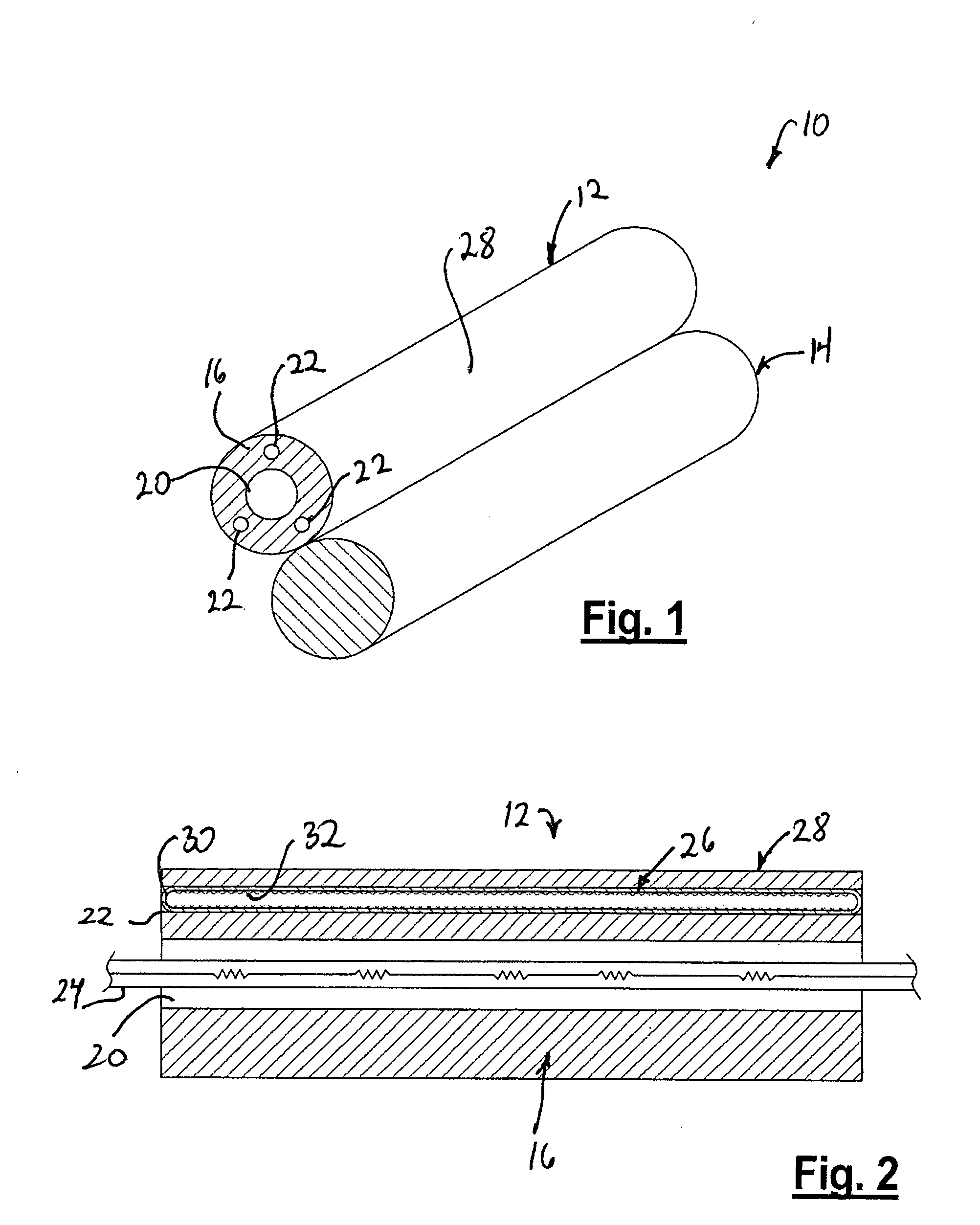
[0014]Referring to FIG. 1, there is shown the fusing apparatus of the present invention. The apparatus 10 includes a fuser roller 12 and a pressing roller 14. The fuser roller 12 and the pressing roller 14 are supported by bearings so that each roller may rotate about its central axis. A motor (not shown) rotates the fuser roller 12, the pressing roller 14, or both.

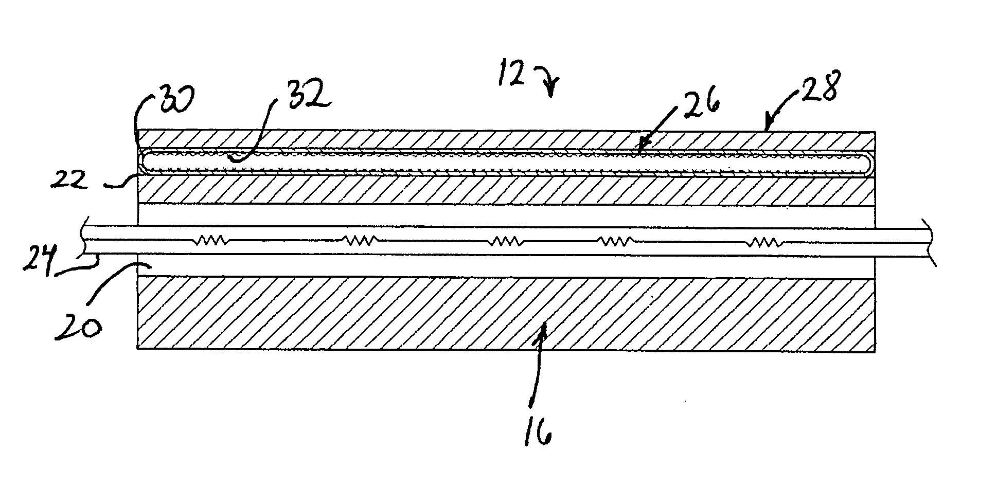
[0015]The fuser roller 12 includes a roller body 16, which is made from a thermally conductive material, such as aluminum or steel, and includes an axial bore 20 and a plurality of radially spaced longitudinal bores 22. The axial bore 20 and the longitudinal bores 22 are formed when extruding the roller body 16 or they are machined into the roller body 16 after it is extruded. As shown in FIG. 2, the axial bore 20 accommodates a heater 24, which comprises one or more lamps, such as halogen lamps.

[0016]The longitudinal bores 22 are each sized for a tight fit with a heat pipe 26, and the longitudinal bore 22, the heat pipe ...


PUM


Abstract

The invention provides a fuser apparatus including a fuser roller and a pressing roller. The fuser roller includes one or more heat pipes situated in longitudinal bores in the roller body. The heat pipes are coated with a thermal interface material for conducting heat between the roller body and the heat pipe.

Description

FIELD OF THE INVENTION[0001]This invention relates to fuser rollers for setting toner on paper in a photocopier, a laser printer, or another electrophotographic machine.BACKGROUND OF THE INVENTION[0002]Photocopiers and laser printers use an electrophotographic process to impermanently apply loose toner powder to a sheet of paper. The toner must be subsequently melted to permanently fuse it with the fibers in the paper. The melting heat is generally applied by passing the paper between a pair of rollers wherein at least one of the rollers is heated by a heat source situated in an axial bore of the heated roller.[0003]A common challenge with fuser rollers is to apply heat evenly to the sheet of paper. The distribution of heat is limited by the heat transfer properties of the fuser roller material. Heat pipes, which can rapidly transfer heat along the longitudinal direction, may be embedded in the roller to draw heat from hot portions of the roller to cooler portions in order to provid...

Claims


Application Information

Patent Timeline
IPC IPC(8): G03G15/20
CPCG03G15/2057
Inventor SCHUMAN, ROBERT
Owner ZINDA MARKETING
Learn More