Spark plug

a technology of spark plugs and spark plugs, which is applied in spark plugs, basic electric elements, electrical equipment, etc., can solve the problems of insufficient heat sinking ability of ground electrodes, and achieve the effect of improving the improving the durability of the electrode, and effective heat sinking ability of the front end portion of the ground electrod

Active Publication Date: 2008-05-29
NGK SPARK PLUG CO LTD
View PDF9 Cites 20 Cited by
  • Summary
  • Abstract
  • Description
  • Claims
  • Application Information

AI Technical Summary

Benefits of technology

[0012]In the spark plug according the first embodiment, since at least either the second part or the third part is disposed on a side towards the edge of the other end of the ground electrode with respect to the first part on the third segment that constitutes the outline of the core material defined by projecting the core material onto the side face of the ground electrode, the core material can be located on the further edge side of the front end portion and close to the outer circumference face. With this composition, in the front end portion of the ground electrode, heat received from a combustion chamber during a drive of an internal-combustion engine can be conducted to the core material from the position on the further front end side and close to the outer circumference face. As a result, more effective heat sinking ability of the front end portion of the ground electrode can be achieved.
[0013]The composition that the core material can be located on the further edge side of the front end portion and close to the outer circumference face is still effective for the case where an electrode tip for improving a durability of an electrode in a spark discharge gap is provided in the front end portion of the ground electrode according to the second embodiment. As mentioned above, in addition to the improvement in the heat sinking ability of the front end portion of the ground electrode, heat that the electrode tip receives can be smoothly conducted to the core material. As a result, the heat sinking ability near the spark discharge gap can be further improved.
[0014]When such an electrode tip is bonded to the front end portion of the ground electrode through the resistance welding, heat produced in a welding area at the time of bonding is conducted through the core material whereby it is unlikely to obtain sufficient bonding strength. In this case, as in the present invention according to the third embodiment, the fourth part on the outline of the bonding face of the electrode tip which is defined by projecting the bonding face onto the side face of the ground electrode is located between the first part on the outline of the core material and at least either the second part or the third part in the first direction. With this composition, a portion can be reliably provided where the outline of the electrode tip and that of the core material defined by projecting the electrode tip and the core material, respectively, onto the side face of the ground electrode do not overlap each other, thereby preventing heat during the resistance welding from being conducted to the core material. As a result, the electrode tip and the ground electrode can be further effectively bonded together. On the other hand, since at least either the second part or the third part since on the outline of the core material is disposed on the further front end side of the ground electrode with respect to the fourth part on the outline of electrode tip, the core material and the electrode tip are disposed close to each other in the light of the relation between the first part on the outline of the core material and the fourth part on the outline of the electrode tip. Thus, heat that the electrode tip receives can be smoothly conducted to the core material whereby the heat sinking ability near the spark discharge gap can be further improved.
[0015]Further, as in the present invention according to the fourth embodiment, when the outline of the bonding face of the electrode tip and that of the core material are kept in the noncontact state, both of which are defined by projecting the bonding face and the core material, respectively, onto the side face of the ground electrode, heat during the resistance welding is more effectively prevented from being conducted to the core material, thereby improving the bonding strength. Furthermore, since the core material can extend towards the further front end side of the front end portion by diverting the position of the electrode tip, the heat that the electrode tip receives can be conducted to the core material whereby the heat sinking ability near the spark discharge gap can be further improved.
[0016]As in the present invention according to the fifth embodiment or the sixth embodiment, when a positional relationship between the outline of the bonding face of the electrode tip and that of the core material both of which are defined by projecting the bonding face and the core material, respectively, onto the side face of the ground electrode is more specifically defined, the bonding strength between the electrode tip and the ground electrode can be sufficiently secured as well as improving the heat sinking ability of the front end portion of the ground electrode including heat conduction from the electrode tip to the ground electrode.

Problems solved by technology

Thus, heat that the front end portion of the ground electrode receives is unlikely to be promptly conducted to the metal shell, and the heat sinking ability of the ground electrode tends to be insufficient.

Method used


Image

  • Spark plug
  • Spark plug
  • Spark plug

Examples


Embodiment Construction

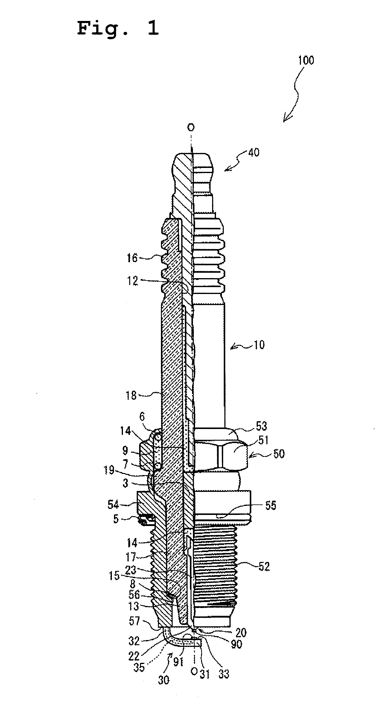
[0029]Hereafter, an embodiment of a spark plug embodying the present invention will be described with reference to the drawings. First, referring to FIG. 1, a composition of a spark plug 100 will be explained. FIG. 1 is a partial sectional view of the spark plug 100. It is noted that, in the axial direction “O”, a side where a center electrode 20 is accommodated in an axial bore 12 of an insulator 10 is regarded as a front end side of the spark plug 100, and a side where a terminal metal fitting 40 is held is regarded as a rear end side of the spark plug 100 in the specification.

[0030]As shown in FIG. 1, the spark plug 100 is comprised of: an insulator 10; a metal shell 50 provided in a generally central portion of the insulator 10 in the longitudinal direction and holding the insulator 10; a center electrode 20 accommodated in an axial bore 12 of the insulator 10 in the axial direction; a ground electrode 30 having one end (a base portion 32) welded to a front end face 57 of the me...


PUM


Abstract

A spark plug including a ground electrode which has an excellent heat sinking ability. The ground electrode includes a core material therein. Heat received from a combustion chamber during a drive of an internal-combustion engine can be conducted to the core material. More effective heat sinking ability can be achieved because of the core material.

Description

FIELD OF THE INVENTION [0001]The present invention relates to a spark plug used for internal-combustion engines and including a ground electrode which has a metal-made core material excellent in thermal conductivity.BACKGROUND OF THE INVENTION [0002]Conventionally, a spark plug is used for igniting an internal-combustion engine. An ordinary spark plug is comprised of: a metal shell radially surrounding and holding a circumference of an insulator in which a center electrode is accommodated in an axial bore; and a ground electrode in which one end thereof is joined to a front end of the metal shell and the other end thereof is bent towards a front end of the center electrode so as to face each other and form a spark discharge gap therebetween. Such a spark plug tends to be exposed at a high temperature because the ground electrode projects to a combustion chamber when the spark plug is attached to an engine head. Thus, since the heat load applied to the ground electrode becomes greate...

Claims


Application Information

Patent Timeline
Patent Type & Authority Applications(United States)
IPC IPC(8): H01T13/32
CPCH01T13/32
Inventor KISHIMOTO, KAORINAKAYAMA, KATSUTOSHIKAMEDA, HIROYUKISAKAKURA, YASUSHI
Owner NGK SPARK PLUG CO LTD
Why Eureka
Try Eureka