
Electrochemical Sensor and Method of Manufacture

a technology of electrochemical sensors and manufacturing methods, applied in the field of electrochemical sensors, can solve the problems of affecting the performance of reference electrodes,

Active Publication Date: 2008-05-29
GEORG FISCHER SIGNET
View PDF11 Cites 2 Cited by
  • Summary
  • Abstract
  • Description
  • Claims
  • Application Information

AI Technical Summary

Benefits of technology

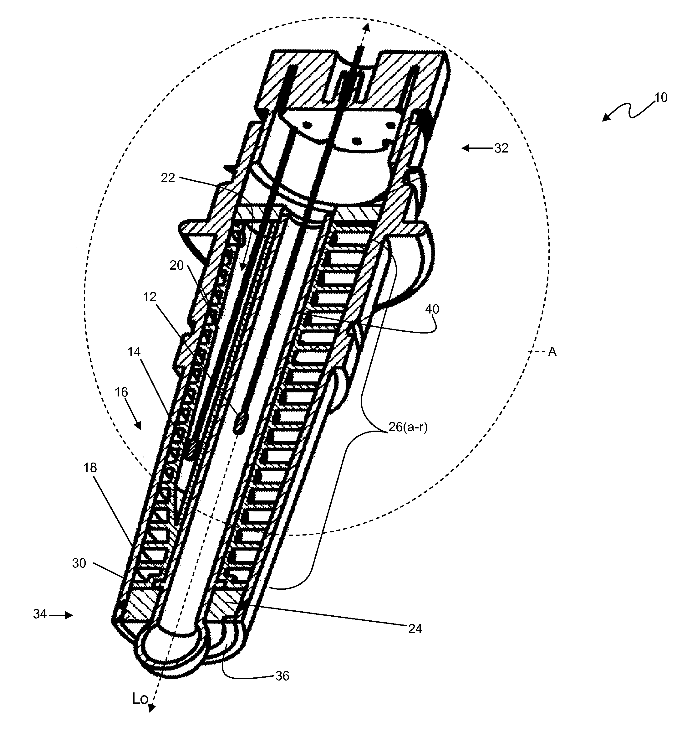
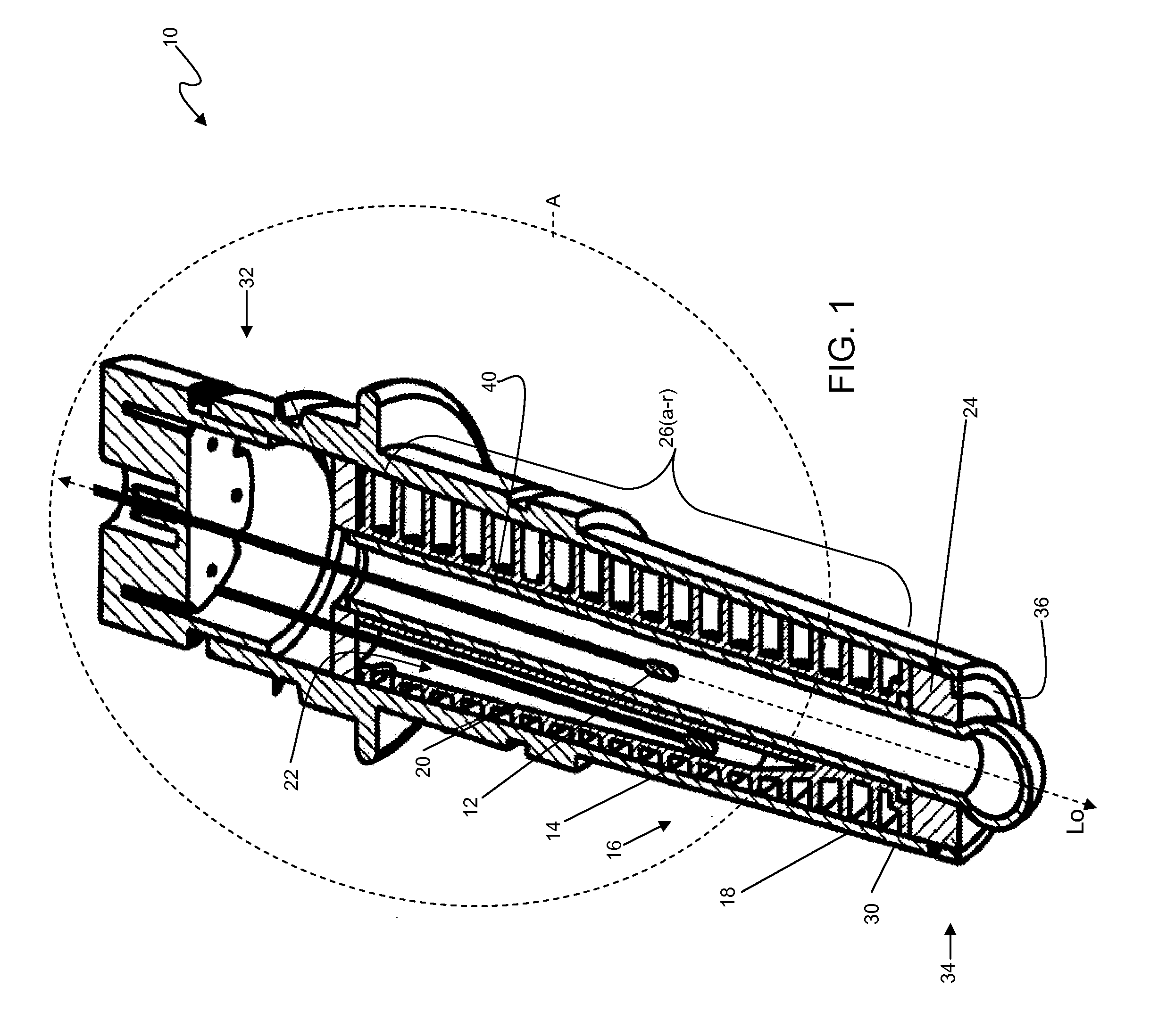
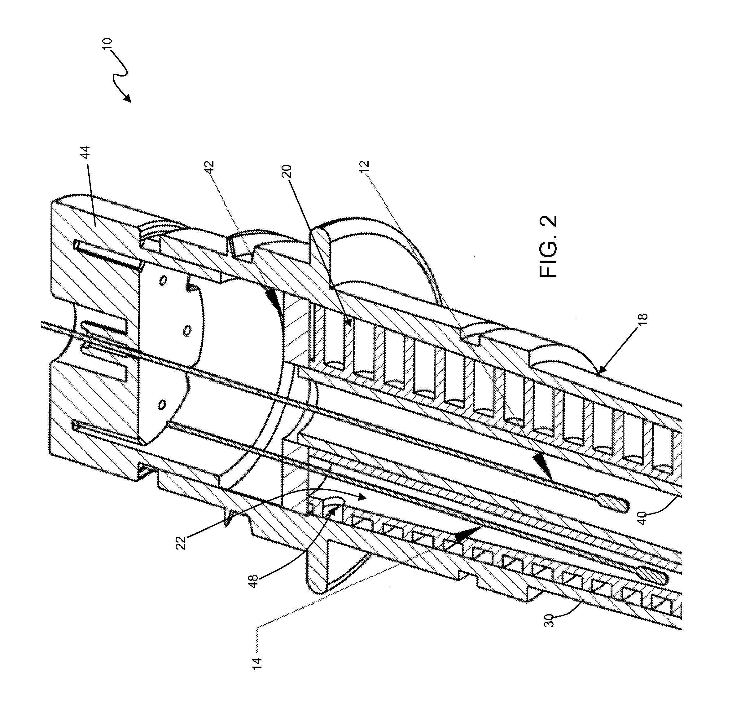
[0008]In general terms, the present invention provides an electrochemical sensor comprising a housing having an outer wall, an axial bore circumscribed by the outer wall, and a barrier wall that aids in defining a reference cavity. The housing further including a plurality of cross members in spaced relation to one another disposed between the axial bore and the outer wall, each cross member defining an aperture. A junction plug is disposed at the distal end of the housing. The junction plug comprises a porous material that enables ionic flow through the junction plug. The sensor enables ionic communication between the target fluid and the reference electrode within the reference cavity passes through the apertures of the plurality of cross members. In this manner, the sensor provides generally a long, tortuous flow path, or salt bridge, between the target fluid and the reference electrode, resulting in a high resistance factor for the sensor.

Problems solved by technology

Contamination or dilution of the reference electrolyte can unduly inhibit performance of the reference electrode, which is of particular concern when used in harsh chemical environments.
Although generally effective, such approaches are relatively expensive and time-consuming to manufacture.
Moreover, performance of such approaches can deteriorate with time.

Method used


Image

  • Electrochemical Sensor and Method of Manufacture
  • Electrochemical Sensor and Method of Manufacture
  • Electrochemical Sensor and Method of Manufacture

Examples


Embodiment Construction

[0025]Referring now to the drawings, and particularly to FIGS. 1 and 2, there is shown an electrochemical sensor assembly 10, for measuring parameters of a target fluid (not shown), such as ORP or specific ions, e.g., pH or sodium. The sensor assembly 10 includes a measuring electrode 12 (e.g., glass pH electrode) and a reference electrode 14 coupled to a housing 16, having an outer member 18 and an inner member 20. The reference electrode is disposed within a reference cavity 22, defined by the inner member of the housing, and is surrounded by a reference electrolyte. The sensor assembly includes a liquid junction comprising a junction plug 24 disposed at distal end of the housing. The inner member includes a plurality of cross members 26(a-r), each defining an aperture 28(a-r). The cross members and apertures aid in defining a long, tortuous flow path, or salt bridge, between the target fluid and the reference electrode, resulting in a high resistance factor for the sensor.

[0026]A...


PUM

PropertyMeasurementUnit
Angleaaaaaaaaaa
Flow rateaaaaaaaaaa
Electrical resistanceaaaaaaaaaa

Abstract

An electrochemical sensor is provided that includes a housing having an outer wall, an axial bore circumscribed by the outer wall, and a barrier wall that aids in defining a reference cavity. The housing further including a plurality of cross members in spaced relation to one another disposed between the axial bore and the outer wall, each cross member defining an aperture. A junction plug is disposed at the distal end of the housing. The junction plug comprises a porous material that enables ionic flow through the junction plug. The sensor enables ionic communication between the target fluid and the reference electrode within the reference cavity through the apertures of the plurality of cross members. In this manner, the sensor provides generally a long, tortuous flow path, or salt bridge, between the target fluid and the reference electrode, resulting in a high resistance factor for the sensor.

Description

BACKGROUND OF THE INVENTION[0001]The present invention relates generally to electrochemical sensors and, more particularly, to such sensors having a reference electrode and a measuring electrode for measuring parameters of a target fluid.[0002]Electrochemical sensors have long been used to measure properties of fluids. Such sensors typically include a measuring electrode assembly and a reference electrode assembly, both which are electrically coupled to an instrument that senses the difference in electrical potential between the electrodes. In sensors of this kind, the measuring electrode assembly typically is exposed directly to the target fluid; whereas the reference electrode assembly is immersed in a stable electrolytic solution, i.e., a reference electrolyte. Sensors of this kind further include an ion-permeable separator, commonly referred to as liquid junction or salt bridge, disposed between the reference electrolyte and the target fluid, to enable a closed circuit between t...

Claims


Application Information

Patent Timeline
IPC IPC(8): G01N27/26G01N37/00
CPCY10T29/49002G01N27/4035
Inventor WELLS, STEVENBURKHARDT, GERTTHAI, ANTHONY
Owner GEORG FISCHER SIGNET
Learn More