A liquid resistance mount for automobile engine with three liquid chamber structure

An automotive engine, hydraulic resistance mount technology, applied in power units, mechanical equipment, vehicle components, etc., can solve problems such as insufficient low-frequency dynamic stiffness, reduce peak frequency jog stiffness, etc., to reduce vibration transmission and increase peak frequency. , the effect of reducing the dynamic stiffness

Inactive Publication Date: 2018-10-26
HOHAI UNIV CHANGZHOU
View PDF8 Cites 0 Cited by
  • Summary
  • Abstract
  • Description
  • Claims
  • Application Information

AI Technical Summary

Problems solved by technology

[0004] In order to overcome the defect of insufficient low-frequency dynamic stiffness of the existing liquid resistance mount, the present invention proposes an automobile engine liquid resistance mount with a three-liquid chamber structure, which can increase the peak value of the dynamic stiffness of the liquid resistance mount in the low frequency range Frequency, increase the dynamic stiffness corresponding to the peak frequency point, and reduce the dynamic stiffness at the peak frequency point in the high frequency range

Method used


Image

  • A liquid resistance mount for automobile engine with three liquid chamber structure
  • A liquid resistance mount for automobile engine with three liquid chamber structure
  • A liquid resistance mount for automobile engine with three liquid chamber structure

Examples


Embodiment Construction

[0027] In order to make the object, technical solution and advantages of the present invention more clear, the present invention will be further described in detail below in conjunction with the examples. It should be understood that the specific embodiments described here are only used to explain the present invention, not to limit the present invention.

[0028] The application principle of the present invention will be described in detail below in conjunction with the accompanying drawings.

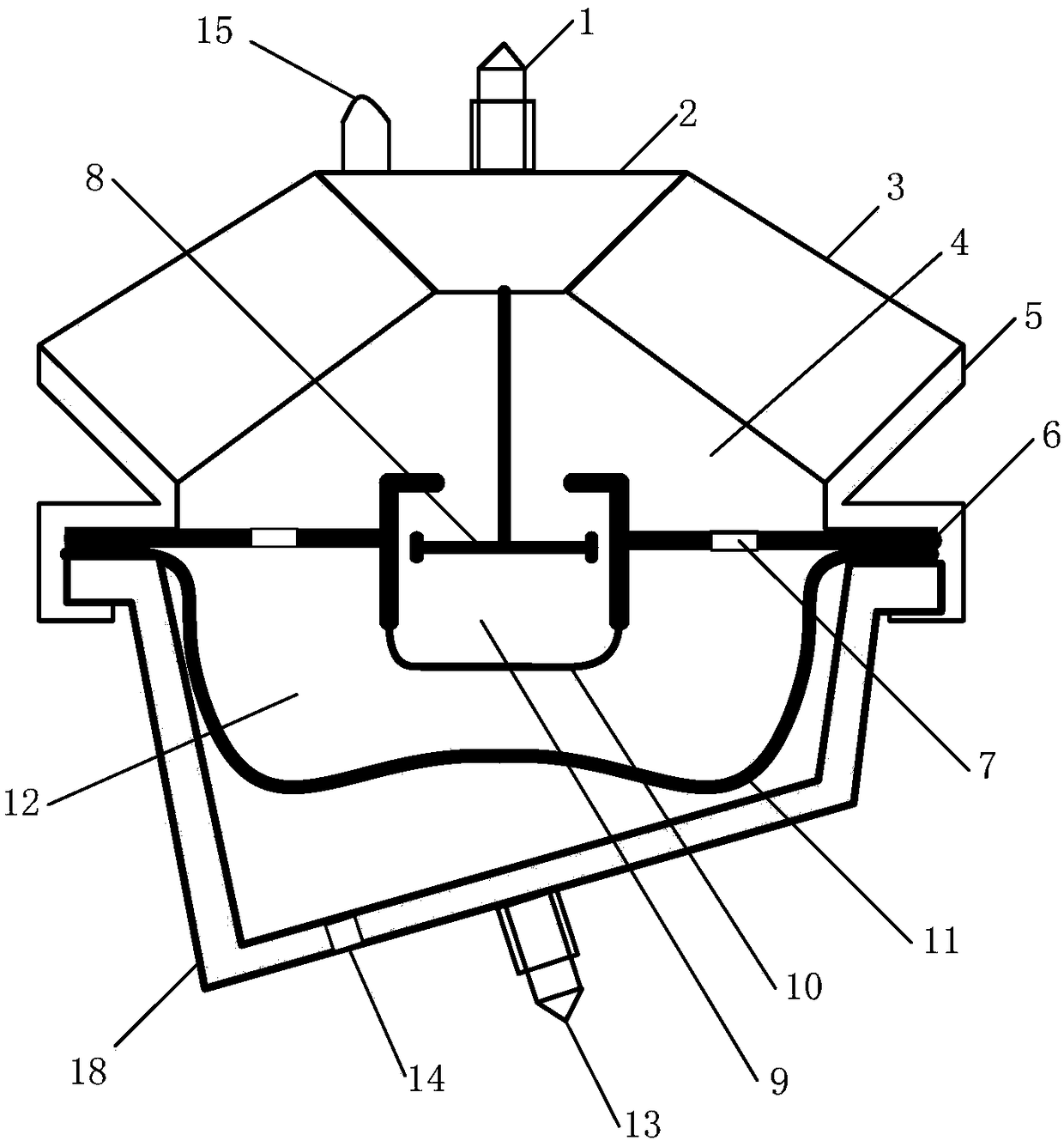
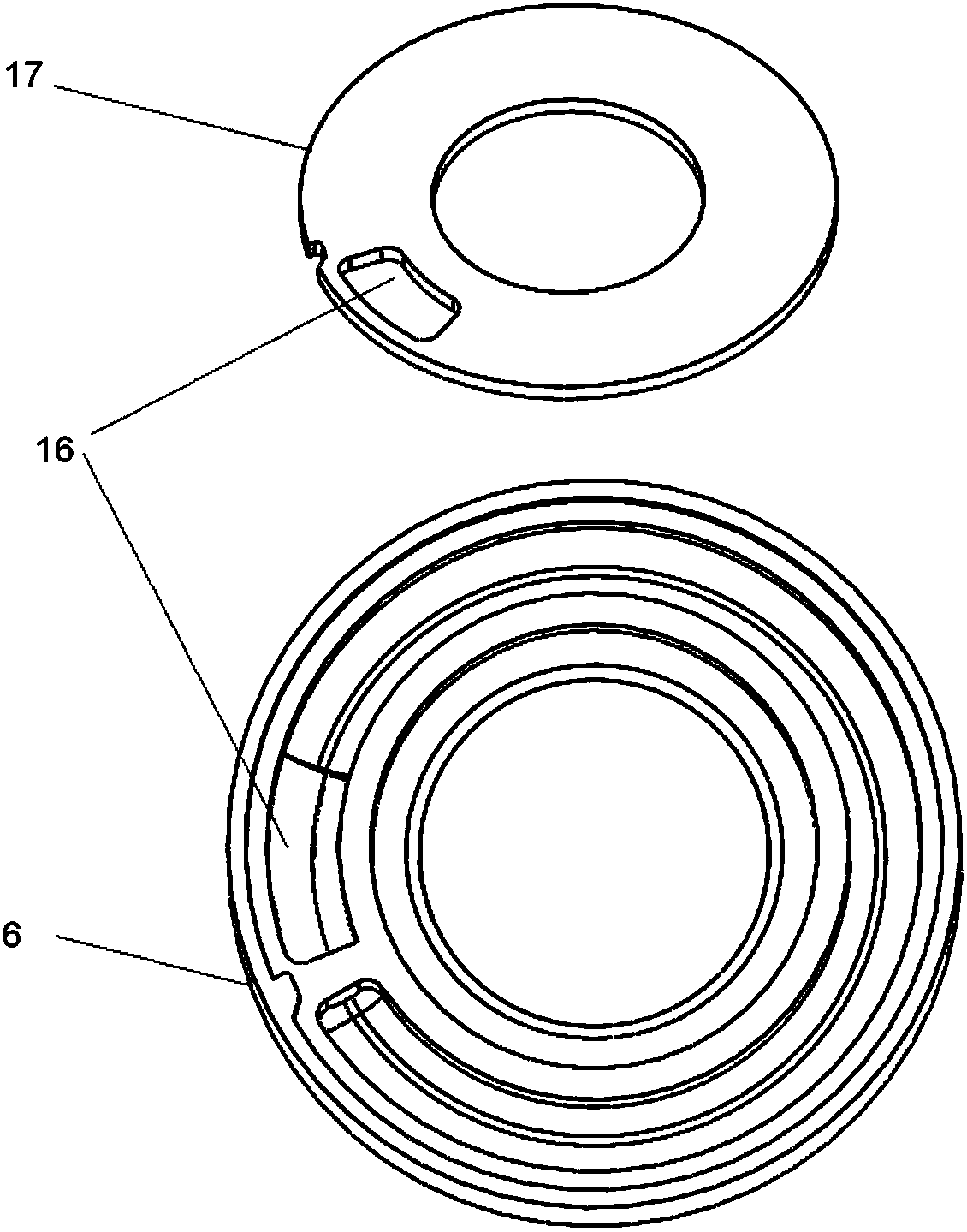
[0029] Such as figure 1 As shown, a kind of automobile engine fluid resistance mount with three liquid chamber structure, comprises support body 2, rubber main spring 3, bracket 5 (in the preferred embodiment of the present invention, it is a circular part), deflector body 6. Rubber bottom film 11, lower end cover 18, decoupling disc 8, rubber diaphragm 10; the rubber main spring 3 is vulcanized into one with the support body 2 and the bracket 5; the two ends of the guide seat body 6,...


PUM


Abstract

The invention discloses an automobile engine hydraulically damped mount with a three-liquid-chamber structure. The automobile engine hydraulically damped mount comprises a supporting body, a rubber main spring, a support, a flow guide base body, a rubber bottom film, a lower end cover, a decoupling disc and a rubber membrane. The rubber main spring together with the supporting body and the support is vulcanized into a whole. The two ends of the flow guide base body, the two ends of the rubber bottom film and the two ends of the lower end cover are all wrapped and pressed by folded edges of the support. The decoupling disc is connected with the supporting body through a connecting rod. An upper liquid chamber is defined by the rubber main spring, the support body and the flow guide base body. A middle liquid chamber is defined by the rubber membrane, the flow guide base body and the decoupling disc. A lower liquid chamber is defined by the flow guide base body and the rubber bottom film. The flow guide base body is provided with an inertia channel. An air chamber is formed by the lower end cover and the rubber bottom film. In the low frequency range, the peak frequency of dynamic stiffness of the hydraulically damped mount is improved, and the dynamic stiffness corresponding to the peak frequency point is improved; and in the high frequency range, the dynamic stiffness corresponding to the peak frequency point is reduced, and the noise reduction and vibration reduction effects of the engine hydraulically damped mount are improved.

Description

technical field [0001] The invention belongs to the field of automobile engine damping components, and in particular relates to an automobile engine liquid resistance mount with a three-liquid chamber structure. Background technique [0002] Automobile engine hydraulic mount is an important vibration reduction and vibration isolation component on the automobile. It plays the role of fixing and supporting the powertrain of the locomotive, isolating the vibration caused by the engine itself and the impact of the road surface. In order to effectively isolate the transmission of the vibration caused by the main harmonic excitation of the reciprocating unbalanced inertial force in the high frequency band of the engine to the car body, improve ride comfort and reduce noise, especially cavity resonance, it is hoped that the suspension components have low stiffness and small damping characteristics; On the other hand, in order to suppress the excitation of the idling fluctuation tor...

Claims


Application Information

Patent Timeline
Patent Type & Authority Patents(China)
IPC IPC(8): F16F13/20F16F13/10B60K5/12
CPCB60K5/1216F16F13/103F16F13/107F16F13/20
Inventor 李堑刘卫博束家龙谭金波
Owner HOHAI UNIV CHANGZHOU
Why Eureka
Try Eureka