
Fixing device for image forming apparatus

a fixing device and image forming technology, applied in the direction of electrographic process apparatus, instruments, optics, etc., can solve the problems of overshooting of the fixing device, adverse affect the fixing performance, and inability to instantaneously control the supplied electric power, so as to improve the fixing performance of the high-speed image forming apparatus, accurate and quick feedback control, and high-quality image

Inactive Publication Date: 2008-05-22
KK TOSHIBA +1
View PDF3 Cites 13 Cited by
  • Summary
  • Abstract
  • Description
  • Claims
  • Application Information

AI Technical Summary

Benefits of technology

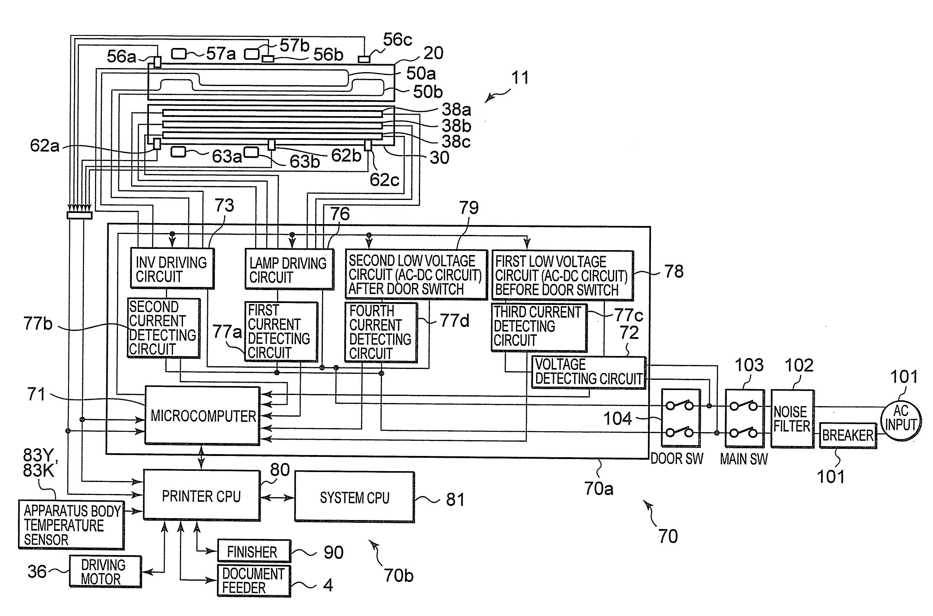
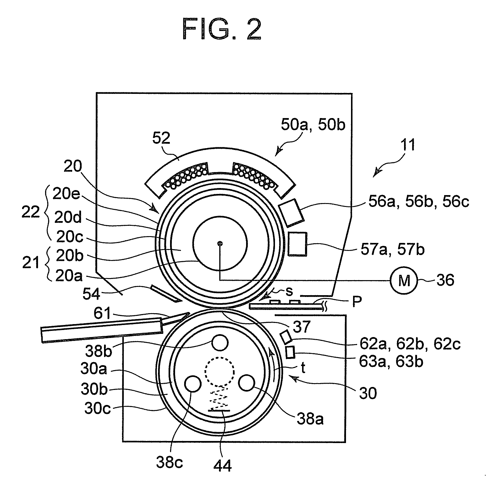
[0008]According to an aspect of the present invention, there is provided a fixing device for an image forming apparatus that accurately and quickly feedback-controls the supply of electric power to an induction heating coil of the fixing device to thereby improve fixing performance of a high-speed image forming apparatus and obtain a high-quality image.

Problems solved by technology

Thus, when the temperature control for the fixing device is delayed, it is likely that fixing performance is adversely affected by the delay.
However, when electric power supplied to the induction heating coil is feedback-controlled using the CPU to subject the fixing device to temperature control as in the past, depending on processing speed of the CPU, it is likely that the supplied electric power cannot be instantaneously controlled.
Since the control is delayed, it is likely that a temperature ripple of the fixing device increases, resulting in overshoot of the fixing device.
Further, it is likely that an optimum fixing temperature corresponding to an operation mode is not obtained and, in particular, temperature control in a high-speed image forming apparatus is difficult.

Method used


Image

  • Fixing device for image forming apparatus
  • Fixing device for image forming apparatus
  • Fixing device for image forming apparatus

Examples


Embodiment Construction

[0013]An embodiment of the present invention will be hereinafter explained in detail with reference to the accompanying drawings.

[0014]FIG. 1 is a schematic structural view showing an image forming apparatus 1 according to the embodiment. The image forming apparatus 1 includes a scanner unit 6 that scans an original, a printer unit 2 that forms an image, and a paper feeding unit 3 that feeds sheet paper P as a recording medium. The scanner unit 6 converts image information scanned from an original supplied by a document feeder 4, which is provided on an upper surface thereof, into an analog signal.

[0015]A door switch 104 is provided on a front side of the printer unit 2. The door switch 104 is switched according to open and close of the front side of the printer unit 2. The printer unit 2 includes an image forming unit 10 in which image forming stations 18Y, 18M, 18C, and 18K for respective colors of yellow (Y), magenta (M), cyan (C), and black (K) are arranged in tandem along a tra...


PUM


Abstract

A fixing device according to an embodiment of the present invention includes a microcomputer that exclusively performs temperature control for the fixing device. The microcomputer periodically calculates electric power that can be supplied to the fixing device. The microcomputer detects the temperature of the fixing device and the temperature in a printer unit and feedback-controls electric power supplied to the fixing device.

Description

CROSS REFERENCE TO RELATED APPLICATION[0001]This invention is based upon and claims the benefit of priority from prior U.S. Patent Application 60 / 866,957 filed on Nov. 22, 2006, the entire contents of which are incorporated herein by reference.BACKGROUND OF THE INVENTION[0002]1. Field of the Invention[0003]The present invention relates to a fixing device mounted on image forming apparatuses such as a copying machine, a printer, and a facsimile, and, more particularly to a fixing device for an image forming apparatus that quickly and highly accurately performs temperature control.[0004]2. Description of the Background[0005]In a fixing device of an induction heating system used in image forming apparatuses of an electrophotographic system such as a copying machine and a printer, in general, the surface temperature of a heat roller is detected and a result of the detection is fed back to an induction heating coil to perform temperature control for the fixing device. In the past, such t...

Claims


Application Information

Patent Timeline
Patent Type & Authority Applications(United States)
IPC IPC(8): G03G15/20
CPCG03G15/2039G03G2215/00772
Inventor NAKAYAMA, HIROSHIDOI, YOHEIKITAMURA, TETSUOTAKAGI, OSAMUKINOUCHI, SATOSHITSUEDA, YOSHINORIKIKUCHI, KAZUHIKOTAKAI, MASANORIKUSAKA, TOYOYASUSONE, TOSHIHIRO
Owner KK TOSHIBA
Learn More