
Look-up table cascade circuit, look-up table cascade array circuit and a pipeline control method thereof

a cascade circuit and array circuit technology, applied in the field of cascade circuits for lookup tables, can solve the problems of difficult rewriting of lut, difficult configuration and control of switchingly connecting a large number of input/output signals, and difficult high-speed operation, so as to achieve high integration and improve the effect of effective operation speed

Inactive Publication Date: 2008-05-22
ELPIDA MEMORY INC
View PDF6 Cites 11 Cited by
  • Summary
  • Abstract
  • Description
  • Claims
  • Application Information

AI Technical Summary

Benefits of technology

[0009]An object of the present invention is to provide a LUT cascade circuit capable of freely writing with convenience and simplicity in configuration and control when configuring the LUT cascade circuit based on the combinational circuit method in which a plurality of LUTs configured in a general memory circuit are connected in cascade with a flexible input / output structure, and to provide a LUT cascade array circuit capable of high-speed processing in which the LUT cascade circuits are operated in parallel by pipeline control.
[0011]According to the configuration of the present invention, the look-up table is configured by the memory cell array, the input select circuit and the output circuit in each stage of the look-up table cascade circuit, and the external input / output signals and the internal input variable are selectively distributed by the connection circuit arranged between the stages. Thereby, it is possible to configure the look-up table cascade circuit based on a combinational circuit method having a highly flexible input / output structure, by adding a small circuit to basic elements of a general memory circuit. In this case, it is possible to flexibly adjust data to be output to outside and data to be transmitted to the subsequent stage, both of which are among the output variable of the look-up table at a predetermined position, by appropriately setting the connection information given to the connection circuit. Particularly, when a large number of look-up tables are used, it is suitable for a configuration capable of operating at high speed with a small circuit scale.
[0025]As described above, according to the present invention, the look-up table cascade circuit is configured using a general memory circuit and its additional circuit in which the memory cell arrays, the input select circuits, the output circuits and the connection circuits are arranged. Based on the input variable distributed by the connection circuit in accordance with the output variable from the preceding stage and the external input variable, a bit line and a word line are selected for data to be read in each memory cell. In this case, the look-up table of each stage has a flexible input / output structure, which can be freely changed in accordance with a setting of the connection information for the connection circuit. Accordingly, an efficient and highly integrated look-up table cascade circuit can be configured without complexity in circuit configuration and control, and write operation for each look-up table can be freely performed by utilizing the input / output path different from the connection circuit in the memory circuit.
[0026]Further, the look-up table cascade array circuit capable of performing various functions can be achieved by arranging the look-up table cascade circuits of the present invention in an array form. In this case, the look-up tables at the same position of different cascade connections can share the word line or the signal path, thereby achieving operations under the pipeline control. Accordingly, different look-up table cascade circuits can be operated in parallel, thereby improving the effective operation speed.

Problems solved by technology

Flexible control can be performed by employing the sequential circuit method, but it is a problem that high-speed operation is difficult because of using the sequencer.
Further, in order to realize the highly flexible structure using the above connection circuit, configuration and control for switchingly connecting a large number of input / output signals become complicated.
Furthermore, since this configuration assumes read operation for each LUT included in the LUT cascade circuit, it is not easy to rewrite the LUT by writing operation of desired data.
Particularly, when the number of stages of the LUT cascade circuit becomes large, it is a problem that the scale of the entire circuit including a large number of LUTs and a large number of connection circuits increases and complexity in control arises.
However, when signal lines or control signals from / to the outside are commonly used in the above conventional combinational circuit method, it is difficult to operate the LUT cascade circuits different from one another simultaneously.
Accordingly, when arranging the plurality of the LUT cascade circuits, it is difficult to employ pipeline control having an advantage in operating speed.

Method used


Image

  • Look-up table cascade circuit, look-up table cascade array circuit and a pipeline control method thereof
  • Look-up table cascade circuit, look-up table cascade array circuit and a pipeline control method thereof
  • Look-up table cascade circuit, look-up table cascade array circuit and a pipeline control method thereof

Examples


first embodiment

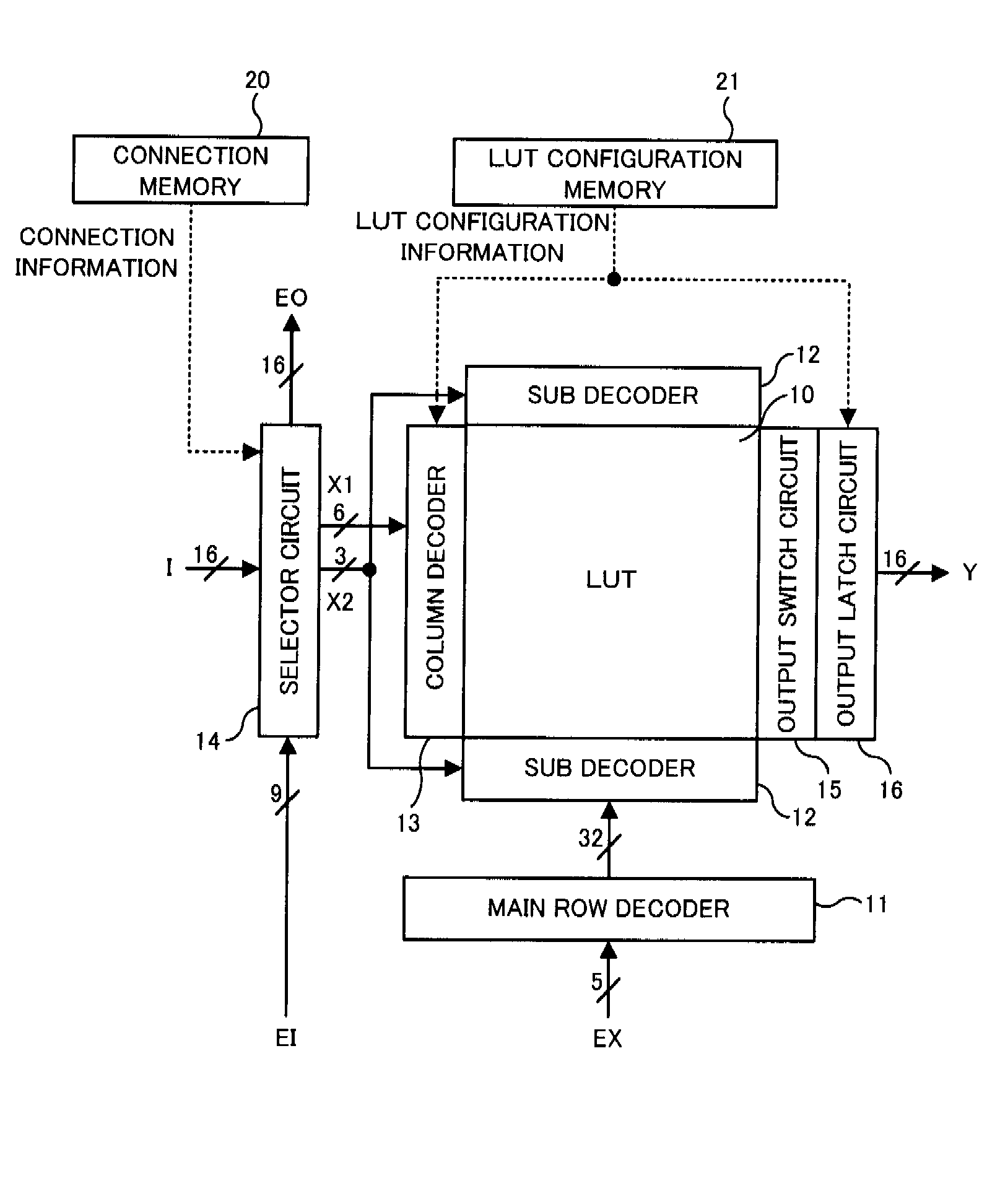
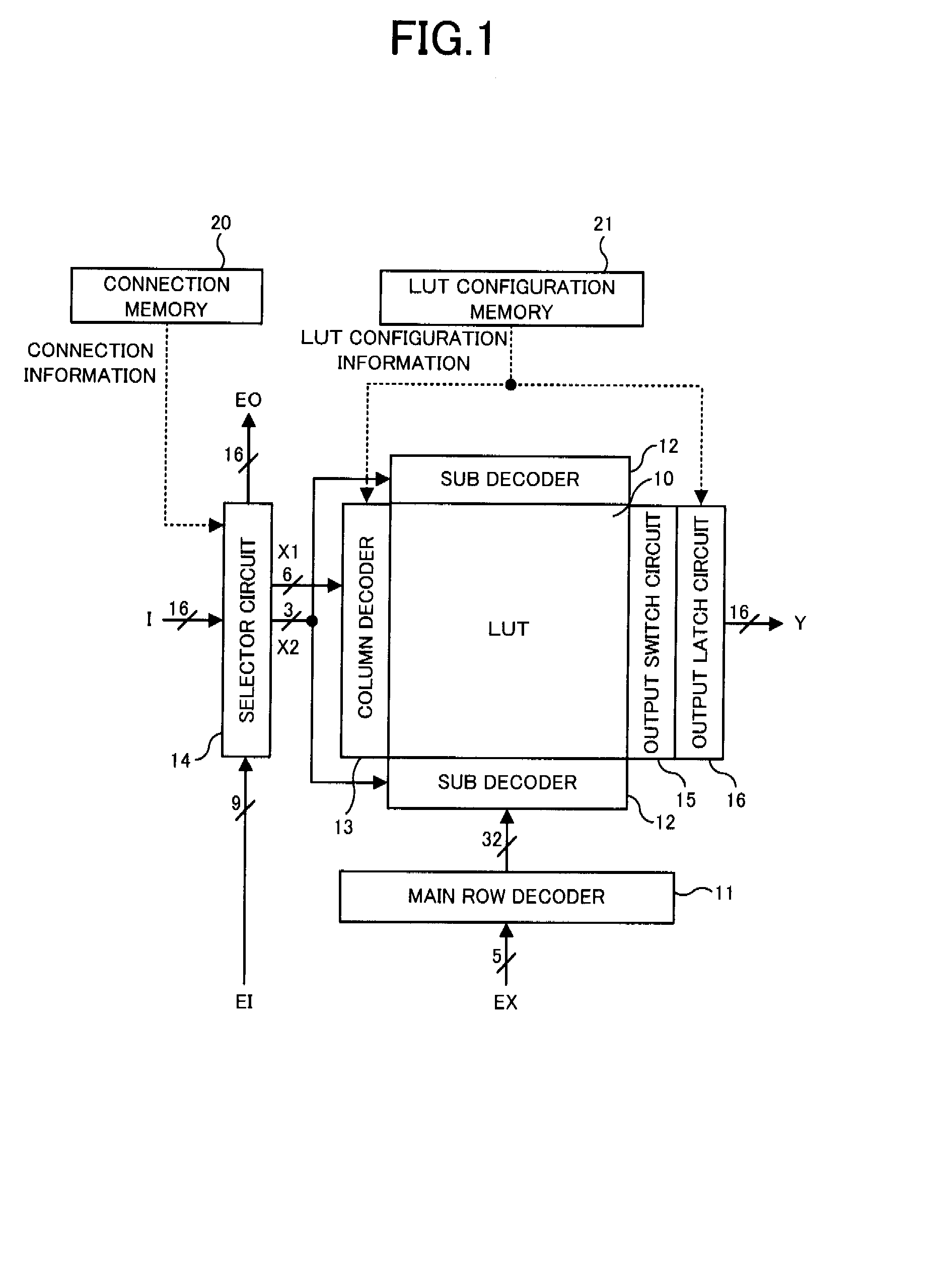
[0048]In a first embodiment, a case will be described in which a LUT cascade circuit having a plurality of LUTs connected in multiple stages is implemented. FIG. 1 a block diagram showing a basic configuration of a unit LUT circuit included in the LUT cascade circuit of the first embodiment. The unit LUT circuit shown in FIG. 1 includes, for example, a circuit required for the function of the LUT, which is added to constituent elements of a general DRAM.

[0049]As shown in FIG. 1, the unit LUT circuit includes a LUT 10 configured in a memory cell array, a main row decoder 11, two sub decoders 12, a column decoder 13, s selector circuit 14, an output switch circuit 15 and an output latch circuit 16. Further, a connection memory 20 for storing connection information and a LUT configuration memory 21 for storing LUT configuration information are arranged on the periphery of the unit LUT circuit.

[0050]The unit LUT circuit of FIG. 1 serves as a predetermined logic function. A 16-bit output...

second embodiment

[0081]In a second embodiment, a case will be described in which a plurality of LUT cascade circuits each having a plurality of LUTs connected in multiple stages is implemented and pipeline control is performed. In the second embodiment, the basic form of the unit LUT circuit are almost common to those of the first embodiment, and configuration and operations are the same as those in FIGS. 1 to 8, so description thereof will be omitted. Meanwhile, in the unit LUT circuit of the second embodiment, a circuit configuration on the periphery of the two sub decoders 12 attached to the LUT 10 is different from that in the first embodiment.

[0082]FIG. 14 is a diagram showing the circuit configuration of the two sub decoders 12 and its periphery in the second embodiment. The circuit configuration of each sub decoder 12 itself and the function of the two predecoders PD are the same as in the first embodiment. On the other hand, two reset circuits 17 adjacent to the two sub decoders 12 are provi...


PUM


Abstract

A look-up table cascade circuit having N look-up tables connected in cascade for implementing a desired logic function, comprising: N memory cell arrays for storing data of the look-up table in memory cells; N input select circuits for selecting a word line and bit lines to specify memory cells based on an input variable to the look-up table; N output circuits for selectively coupling data in the memory cells selected by the input select circuit to an input / output path and for outputting the data as an output variable of the look-up table; and N−1 connection circuits arranged between each preceding output circuit and each subsequent input select circuit, for receiving an external input variable and the output variable output from each preceding output circuit, and for selectively distributing all or part of an external output variable and the input variable based on connection information.

Description

BACKGROUND OF THE INVENTION[0001]1. Field of the Invention[0002]The present invention relates to a look-up table cascade circuit in which a plurality of look-up tables for implementing a desired logic function are connected in cascade, and particularly relates to a look-up table cascade circuit configured using a general memory circuit, and a look-up table cascade array circuit in which the look-up table cascade circuits are arranged in an array form.[0003]2. Description of the Related Art[0004]In recent years, in order to realize LSI having various functions, techniques for configuring a look-up table (LUT) on a memory have been proposed (for example, see “On Look-Up Table Cascade Architecture” IEEJ (The Institute of Electrical Engineers of Japan) Electronics, Information and Systems Society MC2-4, Aug. 29 and 30, 2003; Yukihiro Iguchi and Tsutomu Sasao). In this technique, a LUT cascade circuit in which LUTs are connected in multiple stages in cascade is disclosed to perform a com...

Claims


Application Information

Patent Timeline
Patent Type & Authority Applications(United States)
IPC IPC(8): G11C8/00
CPCG11C7/1006G11C2207/002G11C11/4076G11C7/1045
Inventor KAJIGAYA, KAZUHIKO
Owner ELPIDA MEMORY INC
Learn More