Signal Detector
a signal detector and detector technology, applied in the field of signal detectors, can solve the problems of affecting the noise of electronic devices, the difficulty of switching noise in lighting fixtures, and the difficulty of switching noise in air conditioning, so as to achieve the effect of more accurate detection of signal levels
- Summary
- Abstract
- Description
- Claims
- Application Information
AI Technical Summary
Benefits of technology
Problems solved by technology
Method used
Image
Examples
modification 1
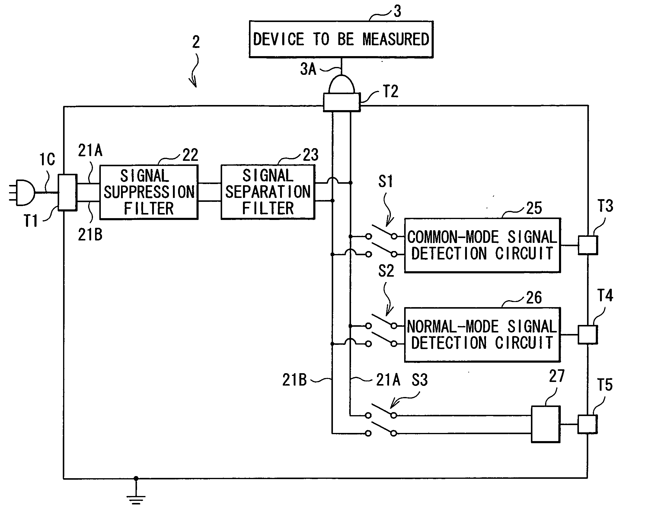
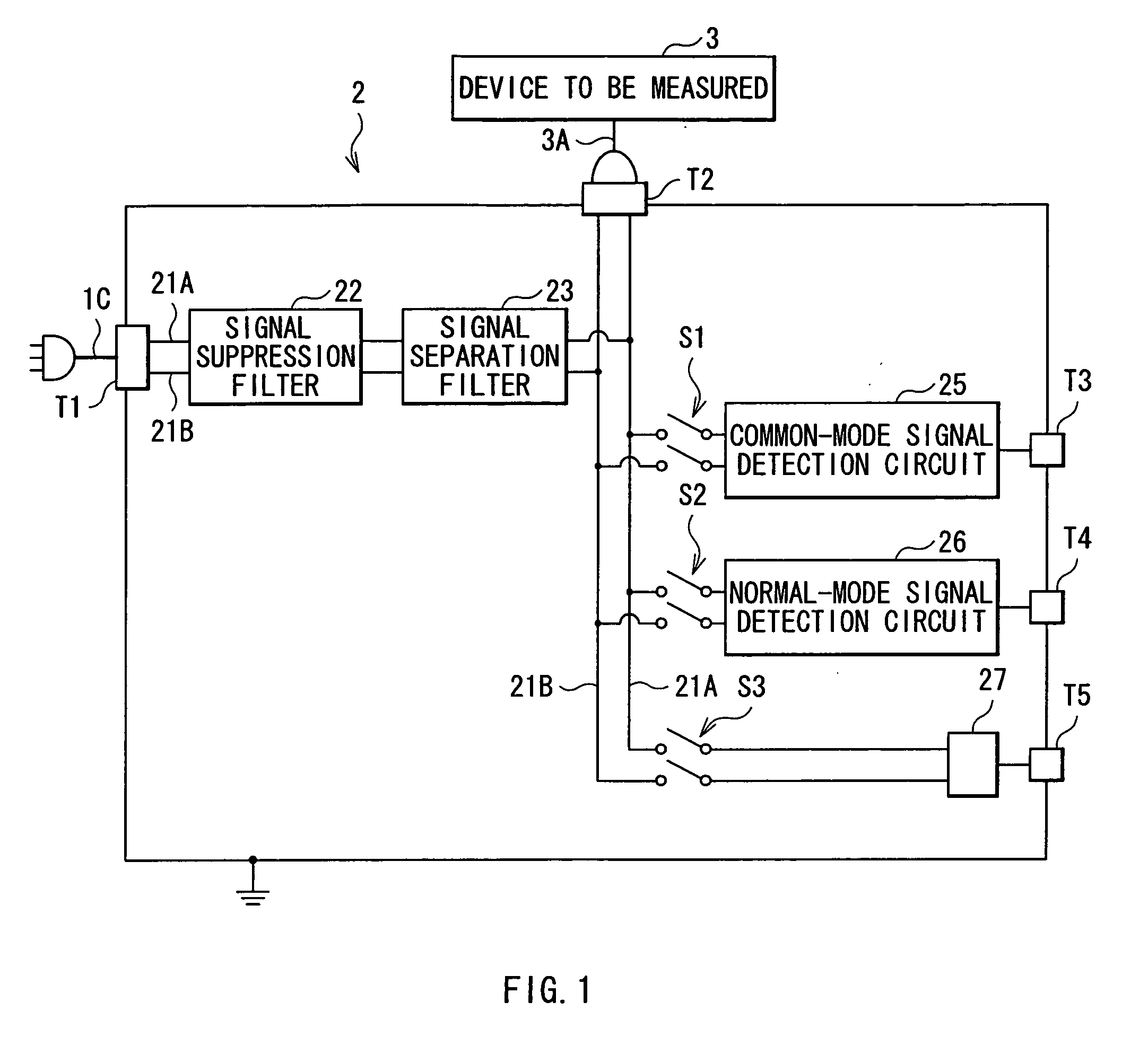
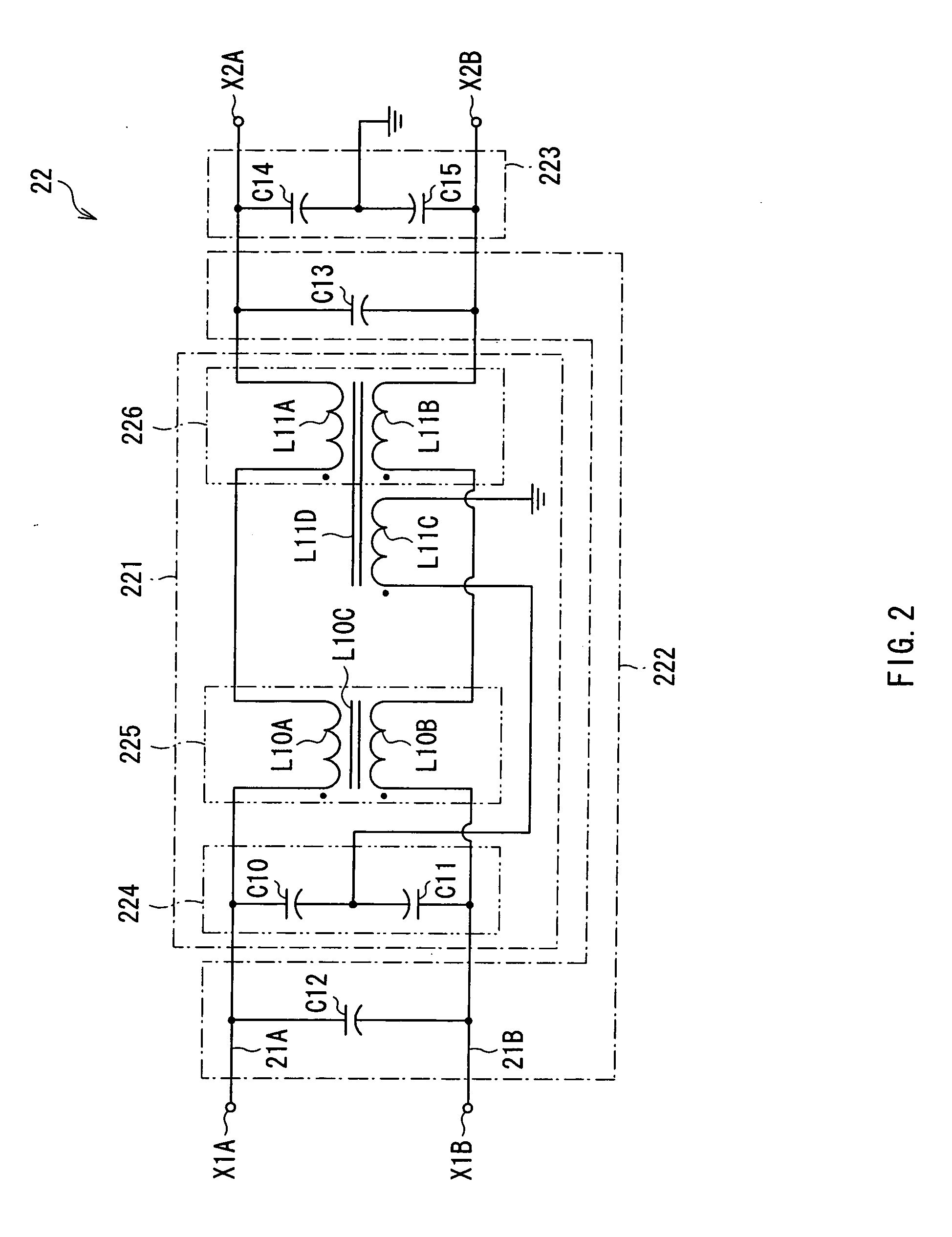
[0117]A modification can be made, in which a normal-mode signal detection circuit 26A as shown in FIG. 8 is used instead of the normal-mode signal detection circuit 26 shown in FIG. 7. The normal-mode signal detection circuit 26A is made to have a configuration similar to that of the common-mode signal cancellation circuit 221 as shown in FIG. 2 by adding an inductance element 264 to a latter stage (side of the terminals X7A, X7B) of the detection-inversion circuit 263 in the common-mode signal cancellation circuit 261 in FIG. 7. The inductance element 264 is the same element as the inductance element 225 in FIG. 2, and includes a winding L10A inserted in a power line 21A, a winding L10B inserted in a power line 21B, and a core L10C. Other configuration is the same as in the case of FIG. 7.
[0118]In the modification, the inductance element 264 generates mutual inductance between the power lines 21A and 21B, which increases impedance to the common mode signal. Therefore, the common mo...
modification 2
[0119]Moreover a modification can be made, in which a common-mode signal detection circuit 25B as shown in FIG. 9 is used instead of the common-mode signal detection circuit 25 shown in FIG. 5. The common-mode signal detection circuit 25B has a normal-mode signal suppression circuit 255 instead of the normal-mode signal cancellation circuit 251 in the common-mode signal detection circuit 25 of FIG. 5, and has a line transforming circuit 258 instead of the line transforming circuit 257.
[0120]The normal-mode signal suppression circuit 255 includes a capacitor C33, an inductance element L31, and a capacitor C34 in order from a side near a high-pass filter 250 on power lines 21A, 21B at an output side of the high-pass filter 250. The capacitor C33 is connected between the power lines 21A and 21B. The inductance element L31 is configured by windings L31A, L31B inserted in the power lines 21A, 21B respectively and a core L31C. The capacitor C33 and the inductance element L31 cooperate wit...
modification 3
[0122]Furthermore, a modification can be made, in which a normal-mode signal detection circuit 26B as shown in FIG. 10 is used instead of the normal-mode signal detection circuit 26 shown in FIG. 7. The normal-mode signal detection circuit 26B has a common mode signal suppression circuit 265 instead of the common-mode signal cancellation circuit 261 in the normal-mode signal detection circuit 26 of FIG. 7. Other configuration is the same as in the normal-mode signal detection circuit 26 of FIG. 7.
[0123]The common mode signal suppression circuit 265 has an inductance element L41 on power lines 21A, 21B at an output side of a high-pass filter 260. The inductance element L41 is configured to include windings L41A, L41B inserted in the power lines 21A, 21B respectively and a core L41C.
[0124]In the normal-mode signal detection circuit 26B in such a configuration, the high-pass filter 260 blocks power supply frequency, and transmits a mixed signal of a common mode signal and a normal mode...
PUM
 Abstract
Description
Claims
Application Information
 - R&D
- Intellectual Property
- Life Sciences
- Materials
- Tech Scout
- Unparalleled Data Quality
- Higher Quality Content
- 60% Fewer Hallucinations
Browse by: Latest US Patents, China's latest patents, Technical Efficacy Thesaurus, Application Domain, Technology Topic, Popular Technical Reports.
© 2025 PatSnap. All rights reserved.Legal|Privacy policy|Modern Slavery Act Transparency Statement|Sitemap|About US| Contact US: help@patsnap.com


