
Acoustic vibration generating element

a technology of generating element and generating element, which is applied in the direction of piezoelectric/electrostrictive transducers, mechanical vibration separation, instruments, etc., can solve the problems of inability to achieve the effect of reducing mechanical quality factor, reducing resonance frequency, and suppressing sound leakag

Active Publication Date: 2008-05-08
TOKIN CORP
View PDF13 Cites 20 Cited by
  • Summary
  • Abstract
  • Description
  • Claims
  • Application Information

AI Technical Summary

Benefits of technology

[0018] It is therefore an object of this invention to achieve a lower resonance frequency, a lower mechanical quality factor Q, and suppression of sound leakage in a bone conduction device, in particular, a bone conduction speaker.

Problems solved by technology

However, the electromechanical transducer of the electromagnetic type is disadvantageous in the following respects.
When the electric current flows through the coil, an energy loss inevitably occurs by a resistance of the coil.
Further, in a low-frequency region, the electric current tends to be excessive because of low impedance so that a load upon the power source is increased.
As a result, a sound output level is inevitably limited in the low-frequency region.
Thus, in the low-frequency region, the sound output level tends to be insufficient.
However, the bone conduction transducer using the piezoelectric element is disadvantageous in the following respects.
Therefore, reproduction in the low-frequency region lower than the resonance frequency is insufficient.
In this event, sound reproduction can not naturally and normally be carried out.
However, if an object equipped with the piezoelectric element is a portable apparatus such as a mobile phone and, therefore, the size of the piezoelectric element is restricted, the technique A has limitations.
However, in this technique, the mechanical strength of the piezoelectric element is lowered.
Therefore, no substantive effect is obtained.
The technique C of adding the mass is disadvantageous in that the mechanical strength tends to be weakened against shocking vibration.
On the other hand, prevention of sound leakage to the surroundings is an unavoidable issue in order to bring the bone conduction speaker into practical use, whether electromagnetic or piezoelectric.

Method used


Image

  • Acoustic vibration generating element
  • Acoustic vibration generating element
  • Acoustic vibration generating element

Examples


first embodiment

Piezoelectric Bimorph Element of a Rectangular Shape

[0049] Preparation was made of a piezoelectric bimorph element having a rectangular shape and comprising two piezoelectric ceramics sheets (manufactured by NEC Tokin under the trade name of NEPEC10®) having the length of 32 mm, the width of 8 mm, and the thickness of 0.15 mm and a shim plate of brass having the length and the width equal to those of the piezoelectric ceramics sheets and the thickness of 50 μm. The piezoelectric bimorph element has a structure in which the shim plate is adhered between the two piezoelectric ceramics sheets by the use of an epoxy adhesive. Hereinafter, the above-mentioned structure will be called a single-plate structure.

[0050] On the other hand, as illustrated in FIG. 4, another piezoelectric bimorph element was produced in the following manner. Preparation was made of two sets of laminated piezoelectric ceramics members 5-1. Each of the laminated piezoelectric ceramics members 5-1 comprises three...

second embodiment

Piezoelectric Bimorph Element of a Circular Shape

[0057] Preparation was made of a piezoelectric bimorph element having a circular shape and comprising two piezoelectric ceramics sheets (manufactured by NEC Tokin under the trade name of NEPEC10®) having the diameter of 30 mm and the thickness of 0.15 mm and a shim plate of brass having the diameter equal to that of the piezoelectric ceramics sheets and the thickness of 50 μm. The piezoelectric bimorph element has a structure in which the shim plate is adhered between the two piezoelectric ceramics sheets by the use of an epoxy adhesive. Hereinafter, the above-mentioned structure will be called a single-plate structure.

[0058] By the use of piezoelectric ceramics sheets made of a material same as the above-mentioned piezoelectric ceramics sheets and having the same diameter and the thickness of 50 μm, a circular piezoelectric bimorph element of a laminated structure was prepared in the manner similar to that described in conjunction ...

third embodiment

Covering Member with V-Shaped Grooves on its Surface

[0065] The acoustic vibration generating element experimentally prepared in the first embodiment was subjected to mechanical machining to form a plurality of V-shaped grooves on two principal surfaces of the covering member of the flexible material (silicone rubber in the embodiment). Each of the V-shaped grooves has a depth of 0.6 mm and extends in a direction perpendicular to a lengthwise direction. Thus, an acoustic vibration generating element according to a third embodiment of this invention was produced.

[0066]FIG. 7 shows the acoustic vibration generating element according to the third embodiment. The piezoelectric bimorph element 1-1 is covered with the covering member 1-2′. The covering member 1-2′ is provided with a plurality of V-shaped grooves 6-1 on its two principal surfaces.

[0067] The acoustic vibration generating element illustrated in FIG. 7 was subjected to measurement using the artificial internal ear in the ma...


PUM


Abstract

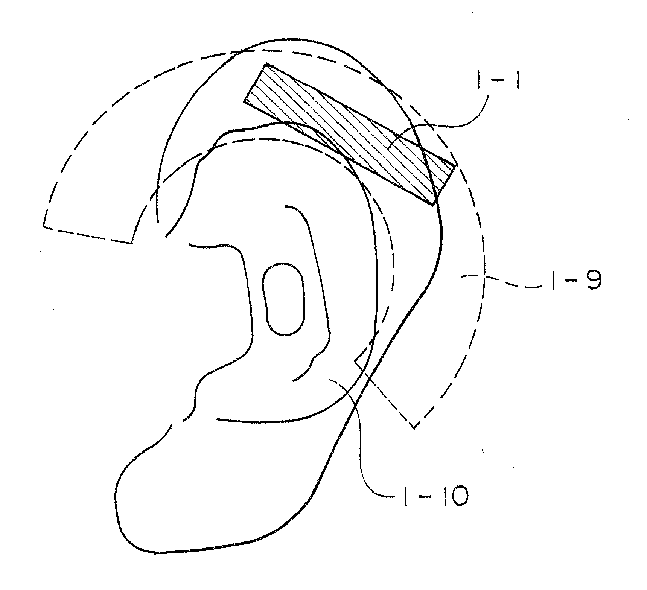
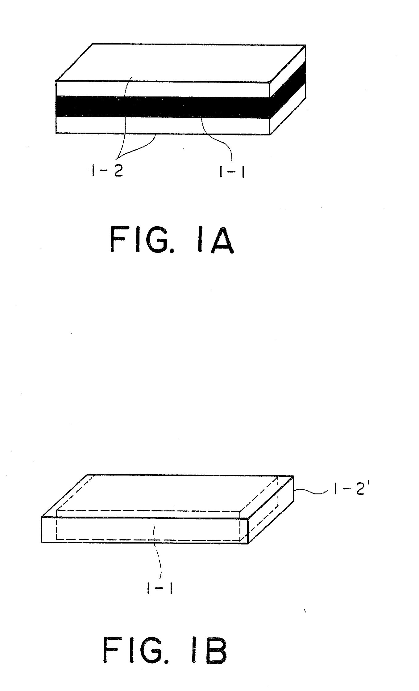
In an acoustic vibration generating element, a piezoelectric bimorph element or unimorph element is covered with a covering member of a flexible material at least on two surfaces perpendicular to a thickness direction. The covering member may be provided with a plurality of V-shaped grooves so as to improve a generated vibrating force. Alternatively, the covering member may be provided with an air chamber in the vicinity of a surface of one side so as to prevent sound leakage. Further, the covering member and an earhook may be integrally formed by the flexible material so as to achieve a light-weight acoustic vibration generating element suitable for a bone conduction speaker.

Description

[0001] The present application is a Divisional Application of U.S. application Ser. No. 10 / 990,117 filed Nov. 15, 2004, which claims priority to prior Japanese patent application JP 2003-414064, the disclosures of which are incorporated herein by reference.BACKGROUND OF THE INVENTION [0002] This invention relates to an acoustic vibration generating element. In particular, this invention is suitable for a bone conduction device, such as a bone conduction speaker, for converting an acoustic electric signal into acoustic vibration to be transmitted to a part of a human body, such as a cranial bone or an arm, so that an acoustic sound is sensed by an auditory nerve. [0003] Heretofore, as an electromechanical transducer for a bone conduction device, use is predominantly made of an electromagnetic type. The electromechanical transducer of the electromagnetic type utilizes a principle same as that of a dynamic speaker and converts a driving force generated by interaction between an electri...

Claims


Application Information

Patent Timeline
Patent Type & Authority Applications(United States)
IPC IPC(8): H04R25/00H04R1/10H04R1/00H04R17/00H04R17/10
CPCH04R17/00H04R2499/11H04R2460/13H04R17/10B06B1/0603G10K9/122H10N30/50
Inventor TAMURA, MITSUO
Owner TOKIN CORP
Learn More