Substrate Treatment Apparatus

a treatment apparatus and substrate technology, applied in the direction of cleaning process and apparatus, chemistry apparatus and process, cleaning using liquids, etc., can solve the problems of poor uniformity and uneven concentration distribution of treatment solution, and achieve high flow rate, high flow rate, and high flow rate

Inactive Publication Date: 2008-05-08
SES CO LTD
View PDF5 Cites 12 Cited by
  • Summary
  • Abstract
  • Description
  • Claims
  • Application Information

AI Technical Summary

Benefits of technology

[0026]The treatment bath 40 for generating swirling currents disclosed in Patent Document 2 and shown in FIG. 12 has a complicated structure. Another treatment bath as disclosed in Patent Document 3 in which substrates are rotated has a further complicated structure. Either case entails difficulties in use and maintenance, and is insufficient for coping with the above-mentioned issues.
[0027]In recent years, the development of such substrate treatment apparatuses capable of processing a large number of substrates with large diameters all at once has been required. For example, to treat a large number of substrates, for example, 50 or more substrates whose diameter is 300 mm or more, treatment baths tend to get larger. Such baths require higher flow rates. Moreover, eliminating foreign matter etc. with high specific gravities requires even higher flow rates.
[0028]On the other hand, securing such high flow rates requires a large amount of a treatment solution, thereby entailing high treatment costs.
[0029]The treatment solution in the above-described treatment baths is either circulated or made into swirling currents. Taking that into account, the inventors of the present invention have found that increasing the flow rate of the swirling currents and changing the directions of the currents at prescribed cycles can work as a solution to the above-mentioned issues and achieved the present invention.
[0030]Accordingly, the present invention is intended to provide a substrate treatment apparatus that is capable of eliminating stagnation of a treatment solution in a treatment bath and providing uniform substrate treatment.
[0031]In addition, the invention is intended to provide a substrate treatment apparatus that facilitates removal of particles.

Problems solved by technology

However, it has been proven that the treatment bath 20 tends to disadvantageously cause stagnation of particles and reaction products at portions Wa to Wc near the periphery of the substrate W as shown in FIG. 10B, resulting in uneven concentration distribution of the treatment solution with poor uniformity.

Method used


Image

  • Substrate Treatment Apparatus
  • Substrate Treatment Apparatus
  • Substrate Treatment Apparatus

Examples


first embodiment

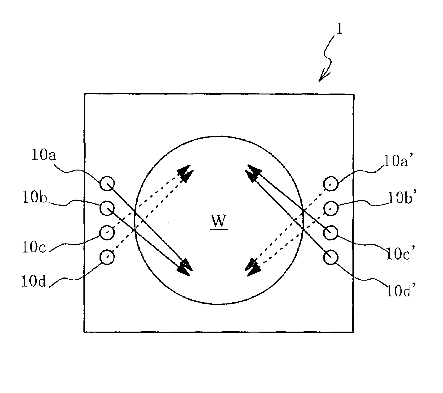
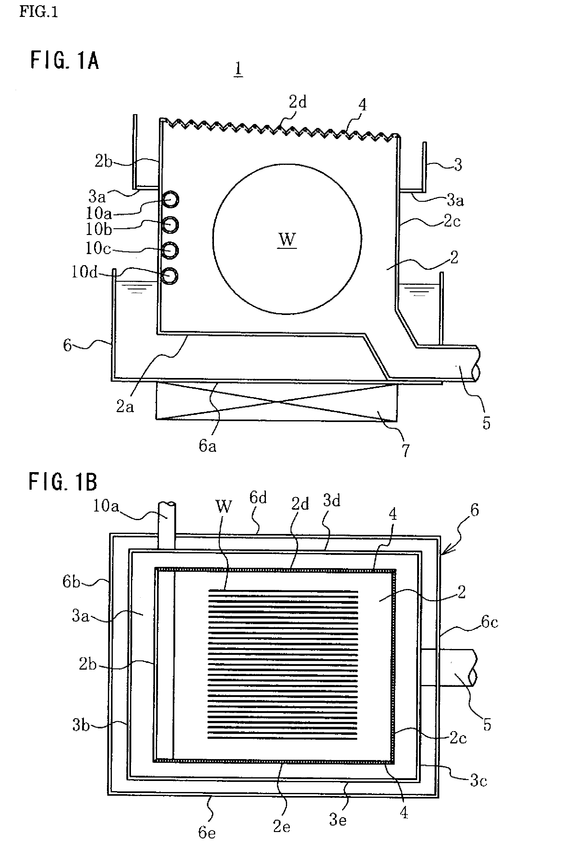
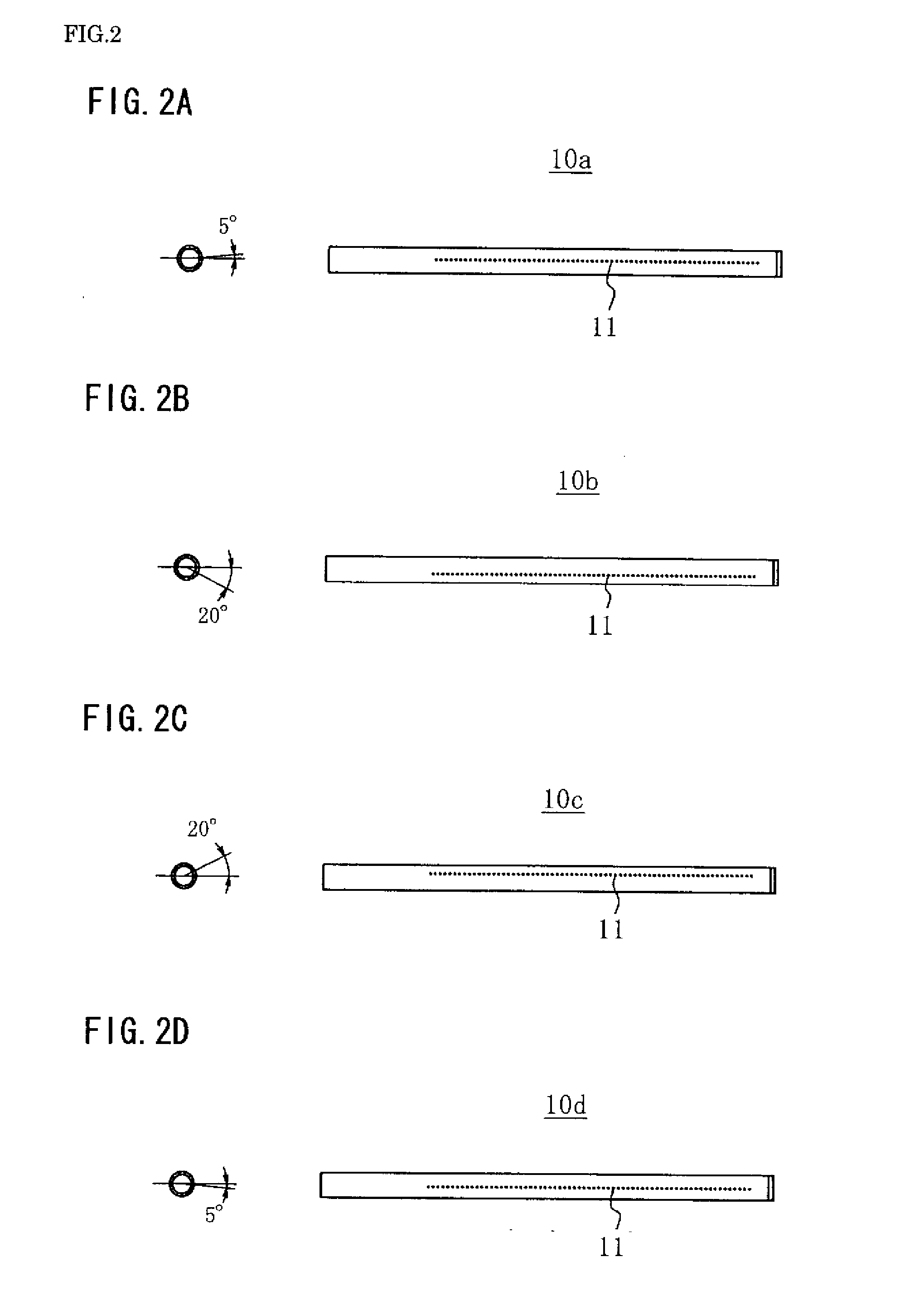
[0100]Showing a treatment bath used in a substrate treatment apparatus according to a first embodiment of the present invention, FIG. 1A is a side sectional view and FIG. 1B is a top view. FIG. 2 is a side view of supplying nozzle tubes disposed in the treatment bath shown in FIG. 1. FIG. 3 shows an embodiment of directions in which the treatment solution supplied from each supplying nozzle tube is ejected. FIG. 4 is a side view showing flows of the treatment solution in the treatment bath. FIG. 5 shows modifications of directions in which the treatment solution supplied from each supplying nozzle tube is ejected.

[0101]This substrate treatment apparatus includes a treatment bath 1. This single bath can be used for a series of surface treatment processes, including chemical and cleansing treatment, for semiconductor wafers, liquid crystal display substrates, recording disk substrates, mask substrates, and various other types of substrates. Representing various types of substrates, a ...

second embodiment

[0132]While the substrate treatment apparatus according to the first embodiment is provided with the plurality of the supplying nozzle tubes on one side of the inner bath, the plurality of supplying nozzle tubes may be provided to both opposite side walls.

[0133]Showing a treatment bath used in a substrate treatment apparatus according to a second embodiment of the present invention, FIG. 6A is a side sectional view and FIG. 6B is a top view. FIGS. 7 and 8 illustrate directions in which the treatment solution supplied from each supplying nozzle tube is ejected.

[0134]This treatment bath 1A have features common to the treatment bath 1 in the first embodiment. Like numerals indicate like elements in the two embodiments and thus repeated description will be omitted. The description of the second embodiment will mainly focus on its features differing from the first embodiment.

[0135]In the treatment bath 1A, as shown in FIG. 6, each of the side walls 2b′ to 2e′ forming the inner bath 2 has...


PUM


Abstract

A substrate treatment apparatus is provided with a treatment bath (1) composed of a bottomed container which is surrounded by side walls (2b-2e) on the four sides and is open at the top, and first and second supplying nozzle tubes (10a-10d) which supply the treatment bath (1) with a treatment solution. The first and second supplying nozzle tubes (10a-10d) are composed of supplying nozzle tubes having a plurality of jetting ports (11) arranged on one line at prescribed intervals on each side plane in a longitudinal direction of the hollow tube-shaped body. The jetting ports of the first supplying nozzle tubes (10b, 10d) among the nozzle tubes are inclined diagonally downward at a prescribed angle from the horizontal direction, the jetting ports of the second supplying nozzle tubes (10a, 10c) are inclined diagonally upward at a prescribed angle from the horizontal direction, and the supplying nozzle tubes are arranged substantially horizontal at prescribed intervals on one side wall plane (2b) of the treatment bath (1). Stagnation of the treatment solution in the treatment bath is eliminated, uniform substrate treatment is made possible and furthermore, particle removal is facilitated.

Description

TECHNICAL FIELD[0001]The present invention relates to a substrate treatment apparatus for treating semiconductor wafers, liquid crystal display substrates, recording disk substrates, mask substrates, and various other types of substrates.RELATED ART [0002]Various types of substrate manufacturing processes, e.g. a semiconductor manufacturing process, include chemical treatment with various types of chemical liquids and cleansing treatment with a rinse liquid to eliminate contaminants attached to the surfaces of a semiconductor wafer (hereinafter referred to as “wafer”) or remove unnecessary oxide or resist films, for example.[0003]To provide such treatment processes in a single treatment bath, a plurality of wafers are placed horizontally upright in the treatment bath. Chemical and rinse liquids are supplied from the bottom of the treatment bath, and circulated in the bath, thereby providing chemical and cleansing treatments.[0004]When the flow of the supplied chemical and rinse liqu...

Claims


Application Information

Patent Timeline
Patent Type & Authority Applications(United States)
IPC IPC(8): B08B3/04H01L21/304B08B3/12
CPCH01L21/67057H01L21/67051H01L21/304
Inventor KIZAWA, HIROSHIKOGA, TAKAHIRONAKATSUKASA, KATSUYOSHIOGASAWARA, KAZUHISAYAMAGUCHI, HIROSHI
Owner SES CO LTD
Why Eureka
Try Eureka