Golf head

a head and golf technology, applied in the field of golf, to achieve the effect of improving bending elasticity, reducing stress on the connecting edge, and improving bending elasticity

Inactive Publication Date: 2008-05-01
CHEN ARCHER C C
View PDF19 Cites 12 Cited by
  • Summary
  • Abstract
  • Description
  • Claims
  • Application Information

AI Technical Summary

Benefits of technology

[0008]In present invention, there are fillisters and flanges on the connecting portion of every part to enhance the structures.
[0009]The plate portion of present invention was designed as a

Problems solved by technology

But, the golf head structures need to consider the combination problem between differ

Method used


Image

  • Golf head
  • Golf head
  • Golf head

Examples


Embodiment Construction

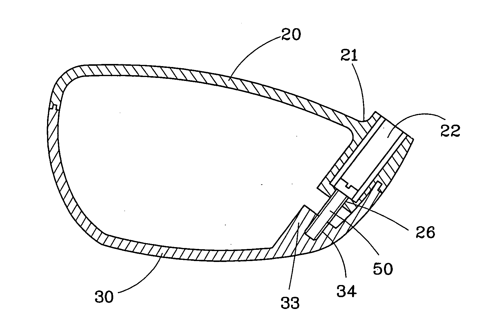
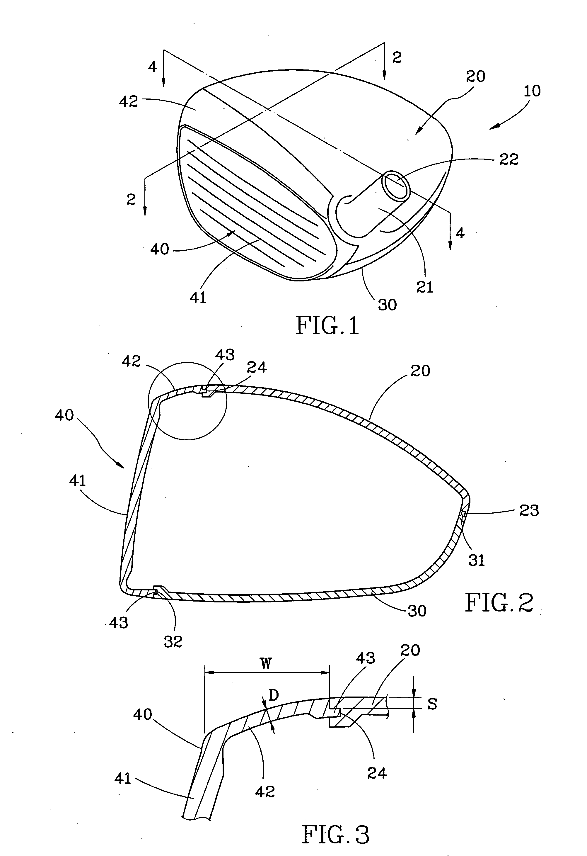
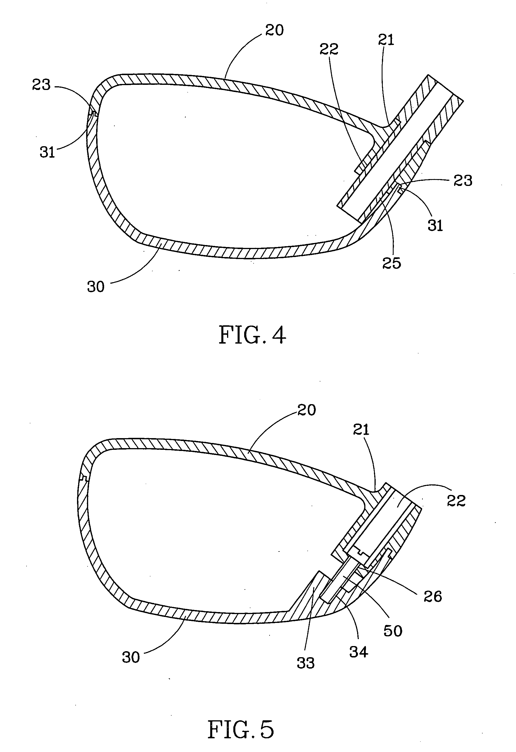
[0015]A golf head 10 of the first embodiment of present invention, comprising:

[0016]A top part 20 makes from light materials like engineering polymers, carbon fiber reinforce resin, magnesium alloy or aluminum alloy with the specific gravity is under 3. The top part provides a neck portion 21 with an axis hole 22 therein for a golf club to plug in.

[0017]A bottom part 30 mounts under the top part 20 and makes from metals like titanium alloy, stainless steel, normal iron materials, tungsten-nickel alloy by powder metallurgy, tungsten-copper alloy by powder metallurgy or the combination of aforesaid materials with the specific gravity is over 4.

[0018]A face part 40 with cup shape has a face 41 and the edge of the face 41 extrudes backward to from a plate potion 42. The face part 40 mounts in front of the bottom part 30 and the top part 20 and makes from elastic metals like titanium alloy, stainless steel or maraging steel.

[0019]Referring to FIG. 2, there is a fillister 23 and a flange ...


PUM


Abstract

A golf head of present invention comprising: A top part makes from light materials with the specific gravity is under 3. The top part provides a neck portion with an axis hole therein for a golf club to plug in. A bottom part mounts under the top part and makes from metals with the specific gravity is over 4. A face part with cup shape has a face and the edge of the face extrudes backward to from a plate potion, the face part mounts in front of the bottom part and the top part and makes from elastic metals like titanium alloy, stainless steel or maraging steel.

Description

BACKGROUND OF THE INVENTION[0001]1. Field of the Invention[0002]The present invention relates to golf and more particularly to golf head with three pieces structures provides special specific weight structures[0003]2. Description of the Related Art[0004]The design of the golf head requires the center-gravity as lower as better. Thus, the weight of the top should be as lighter as better and the face should provide a better elastic strength to prevent breaking and push the ball far away also and to deal with the strong stress from hitting a ball.SUMMARY OF THE INVENTION[0005]The one object of the present invention is to provide golf head with three pieces structures. The top of the golf head is light and the bottom has the character of wear-resisting and center-gravity adjustment and the face provides a better elastic strength. But, the golf head structures need to consider the combination problem between different materials in order to combine different materials to over come the str...

Claims


Application Information

Patent Timeline
IPC IPC(8): A63B53/02A63B53/00
CPCA63B43/02A63B53/0466A63B2053/0408A63B2053/0437A63B2053/0433A63B2209/00A63B2209/023A63B2053/0416A63B53/0408A63B53/0416A63B53/0437A63B53/0433
Inventor CHEN, ARCHER C.C.
Owner CHEN ARCHER C C
Why Eureka
Try Eureka