Powertrain mount for vehicle

a technology for powertrains and vehicles, applied in the direction of machine supports, shock absorbers, jet propulsion mountings, etc., can solve the problems of increased idle vibration, entire vehicles bounce up and down, idle rotation of engines producing so called idle vibration, etc., to achieve the effect of improving the vibration isolation

Inactive Publication Date: 2008-05-01
DTR
View PDF17 Cites 7 Cited by
  • Summary
  • Abstract
  • Description
  • Claims
  • Application Information

AI Technical Summary

Benefits of technology

[0023]It is an object of the present invention to provide a powertrain mount, which has an improved vibration isolation effect for low-frequency vibration, and simultaneously for transient vibration and high-frequency vibration.
[0024]Another object of the invention is to provide a powertrain mount, in which, when mounted in a vehicle, lateral dynamic stiffness of the mount is reduced, relatively to conventional products of same static stiffness vertical to the vehicle, to thereby improve the vibration isolation effect for transient vibration and high-frequency vibration.
[0025]A further object of the invention is to provide a powertrain mount, which can adjust its mounting angle, depending upon vibration-characteristic of a powertrain to be installed in a vehicle, to thereby be able to adjust the capability of insulating vibration.
[0026]In order to accomplish the above objects, according to an aspect of the invention, there is provided a powertrain mount capable of being installed between a powertrain of a vehicle and a structural body of the vehicle supporting the powertrain to isolate vibration being transmitted between the powertrain and the structural body, the powertrain mount comprising: a bracket capable of being mounted on the powertrain or the structural body, the bracket having a rubber holder for receiving and supporting a rubber member thereinside; a slant support means disposed inner side of the rubber holder and disposed slantly with respect to the horizontal plane of the vehicle, the slant support means being provided with a support member connector to which a support member installed in the powertrain can be connected; and a rubber member being bonded with outer circumferential surface of the slant support means while surrounding the slant support means, the rubber member being accommodated in the rubber holder in compressed state but not bonded with the bracket to thereby resiliently support between the slant support means and the bracket, the rubber member having a through-hole formed around both ends in slant direction of the slant support means to thereby reduce dynamic stiffness in slant direction.

Problems solved by technology

When a vehicle is stopped, idle rotation of the engine produces so called idle vibration, due to fluctuation in torque caused by fuel combustion inside the engine.
According to the vibration transmission characteristic, often the vibration frequency being transmitted matches with inherent frequency of the structure of vehicle, the deck cross member, the steering wheel and the muffler to cause resonance, leading to an increased level in the idle vibration.
While traveling at a constant speed on a bumpy road or an unpaved road, the entire vehicle bounces up and down, and experiences rolling and pitching, along with the engine vibration.
Resonance between the suspension and the vehicle body results in significant wobbling of the vehicle.
A powertrain mount provides a major transmission path through which vibration generated in the powertrain is transmitted to the vehicle body, and thus has significant effects on the idle vibration.
In a powertrain system, idle rotation causes mainly low-frequency vibration.
Thus, control of the vibration becomes complicated.
In addition, although improved as compared with the previous technique, it still has a problem that the lateral dynamic stiffness of the mount is higher relative to the static stiffness for supporting the powertrain at the right position.
In case of using the powertrain mount 100 of FIG. 1, accordingly, the vibration control for the powertrain becomes complicated.

Method used


Image

  • Powertrain mount for vehicle
  • Powertrain mount for vehicle
  • Powertrain mount for vehicle

Examples


Embodiment Construction

[0047]Hereafter, exemplary embodiments of the invention will be described, with reference to the accompanying drawings.

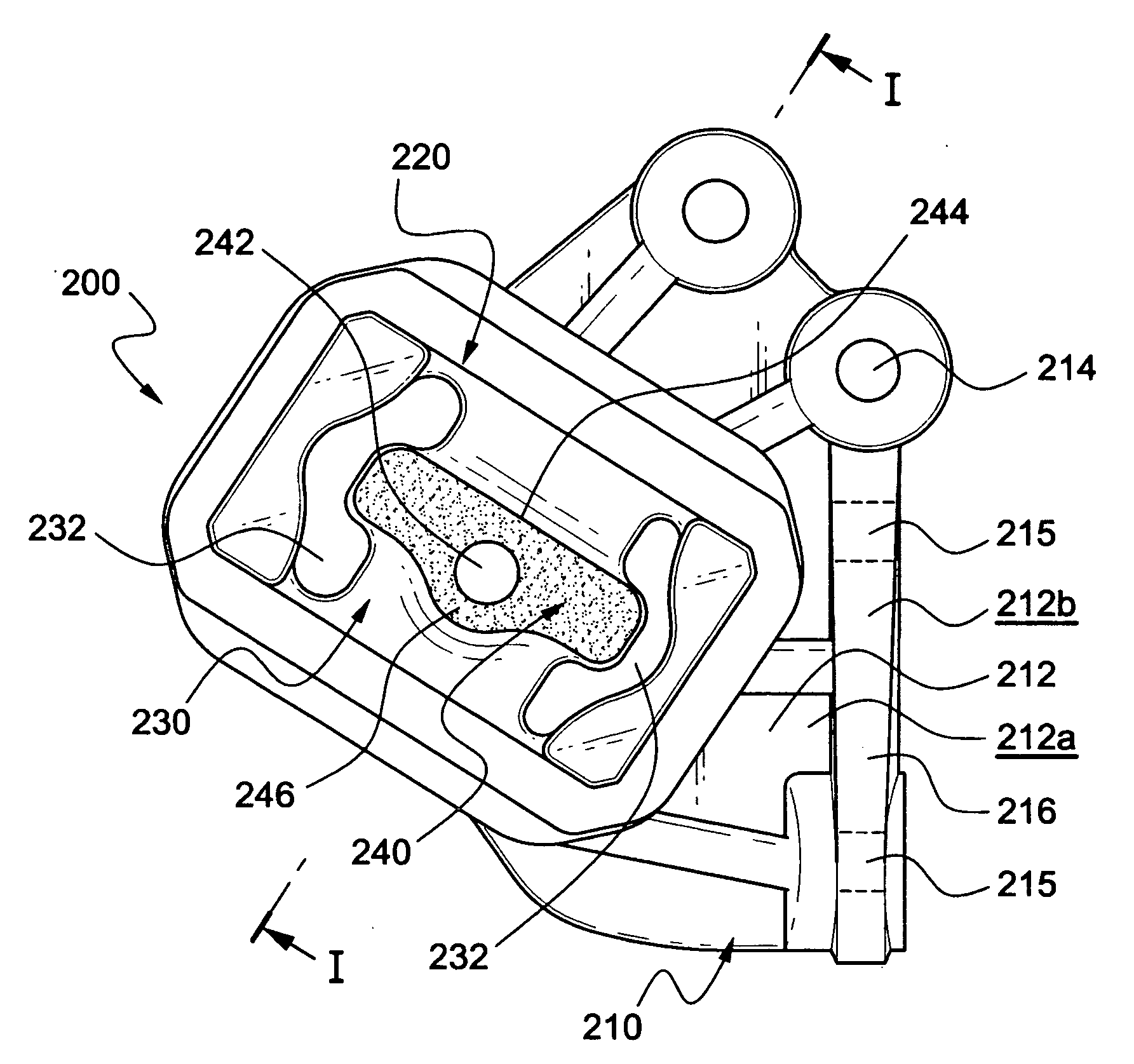
[0048]FIGS. 3 and 4 illustrate a powertrain mount according to an embodiment of the invention where the mount of the invention is generally denoted by reference numeral 200.

[0049]As shown in FIGS. 3 and 4, the powertrain mount 200 of this embodiment is designed so as to be installed between a powertrain of a vehicle and a structural body of the vehicle supporting the power train to thereby isolate vibration being transmitted between the powertrain and the structural body. The powertrain mount 200 is provided with a bracket 210.

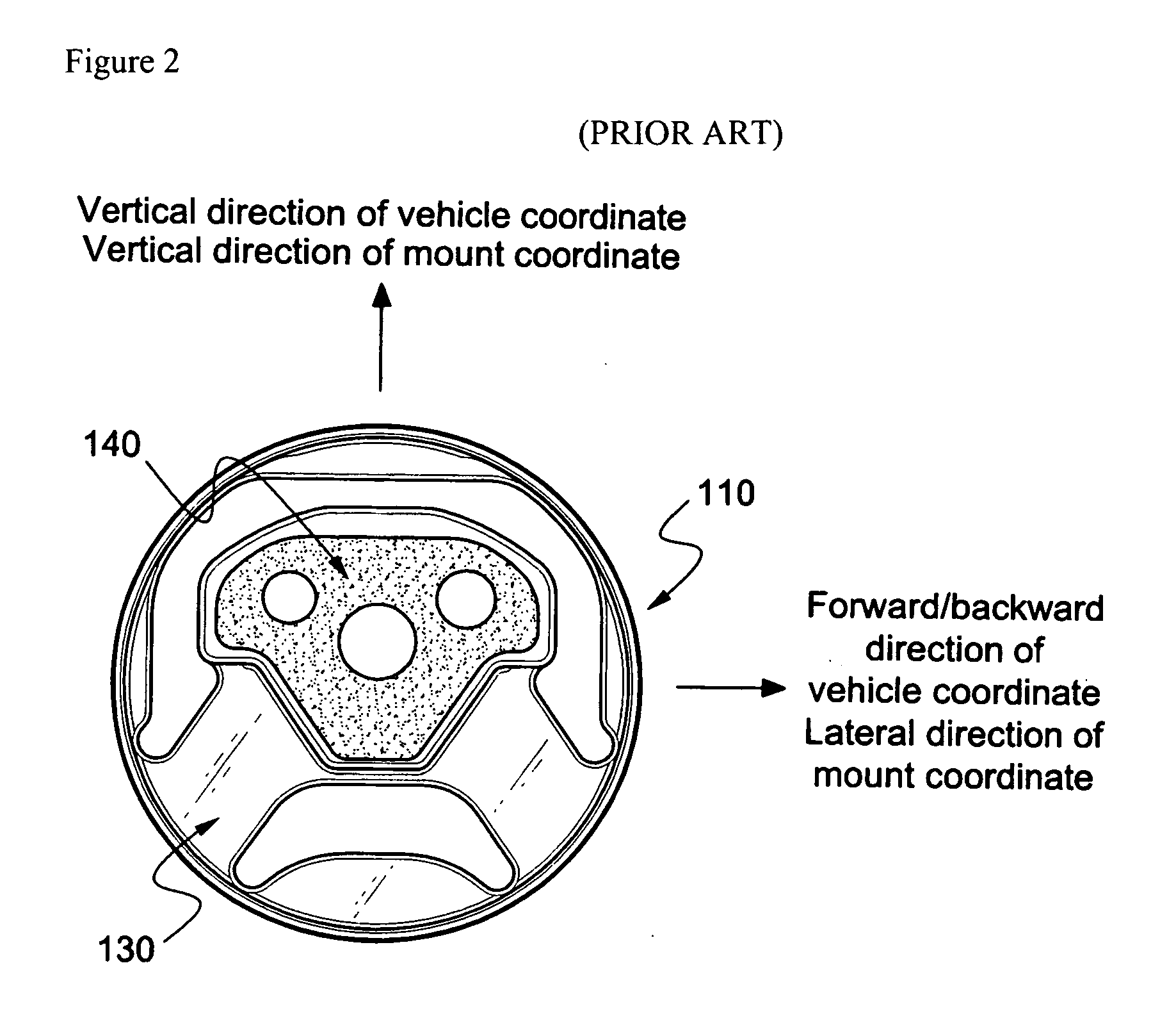
[0050]The powertrain mount 200 of FIGS. 3 and 4 includes a slant support means 240 and the like, which are slant-installed in the engine or the like using the bracket 210. As can be seen in FIG. 5, therefore, the coordinate system of the powertrain mount 200 is different from that of the vehicle, i.e., inclined to one side thereof. Accordingly...


PUM


Abstract

Disclosed is a powertrain mount capable of being installed between a powertrain of a vehicle and a structural body of the vehicle supporting the powertrain to isolate vibration being transmitted between the powertrain and the structural body. The powertrain mount includes a bracket capable of being mounted on the powertrain or the structural body. The bracket has a rubber holder for receiving and supporting a rubber member thereinside. A slant support means is disposed inner side of the rubber holder and disposed slantly with respect to the horizontal plane of the vehicle. The slant support means is provided with a support member connector to which a support member installed in the powertrain can be connected. A rubber member is bonded with outer circumferential surface of the slant support means while surrounding the slant support means. The rubber member is accommodated in the rubber holder in compressed state but not bonded with the bracket to thereby resiliently support between the slant support means and the bracket. The rubber member has a through-hole formed around both ends in slant direction of the slant support means to thereby reduce dynamic stiffness in slant direction.

Description

BACKGROUND OF THE INVENTION[0001]1. Field of the Invention[0002]The present invention relates to a powertrain mount, more particularly to a powertrain mount which is installed between a powertrain such as an engine or transmission of a vehicle and the vehicle structure such as a sub-frame where the powertrain is installed and supported, to thereby isolate vehicle vibration from being transmitted between the powertrain and the vehicle structure.[0003]2. Background of the Related Art[0004]Vehicle vibration occurs in a wide range of frequencies from low to high frequency bands. The vibration may be transmitted to the vehicle body externally from the road surface via the tire and suspension equipment or internally from the engine via the operating system.[0005]When a vehicle is stopped, idle rotation of the engine produces so called idle vibration, due to fluctuation in torque caused by fuel combustion inside the engine. Such engine vibration is transmitted through the steering wheel to...

Claims


Application Information

Patent Timeline
IPC IPC(8): F16F13/00
CPCB60K5/1208F16F1/52F16F1/387
Inventor KIM, TAE SUP
Owner DTR
Why Eureka
Try Eureka