
Fluid port for an adjustable gastric banding system

a gastric banding system and fluid port technology, applied in the field of improved fluid port for use in the gastric banding system, can solve the problems of ultimate failure of the banding system, leakage of fluid into the patient's abdominal cavity, difficulty faced by clinical personnel, etc., to achieve rapid and easy palpation, weight reduction, and increase or decrease the occlusive pressure applied against the stomach

Inactive Publication Date: 2008-04-24
QUEBBEMANN BRIAN B +1
View PDF7 Cites 0 Cited by
  • Summary
  • Abstract
  • Description
  • Claims
  • Application Information

AI Technical Summary

Benefits of technology

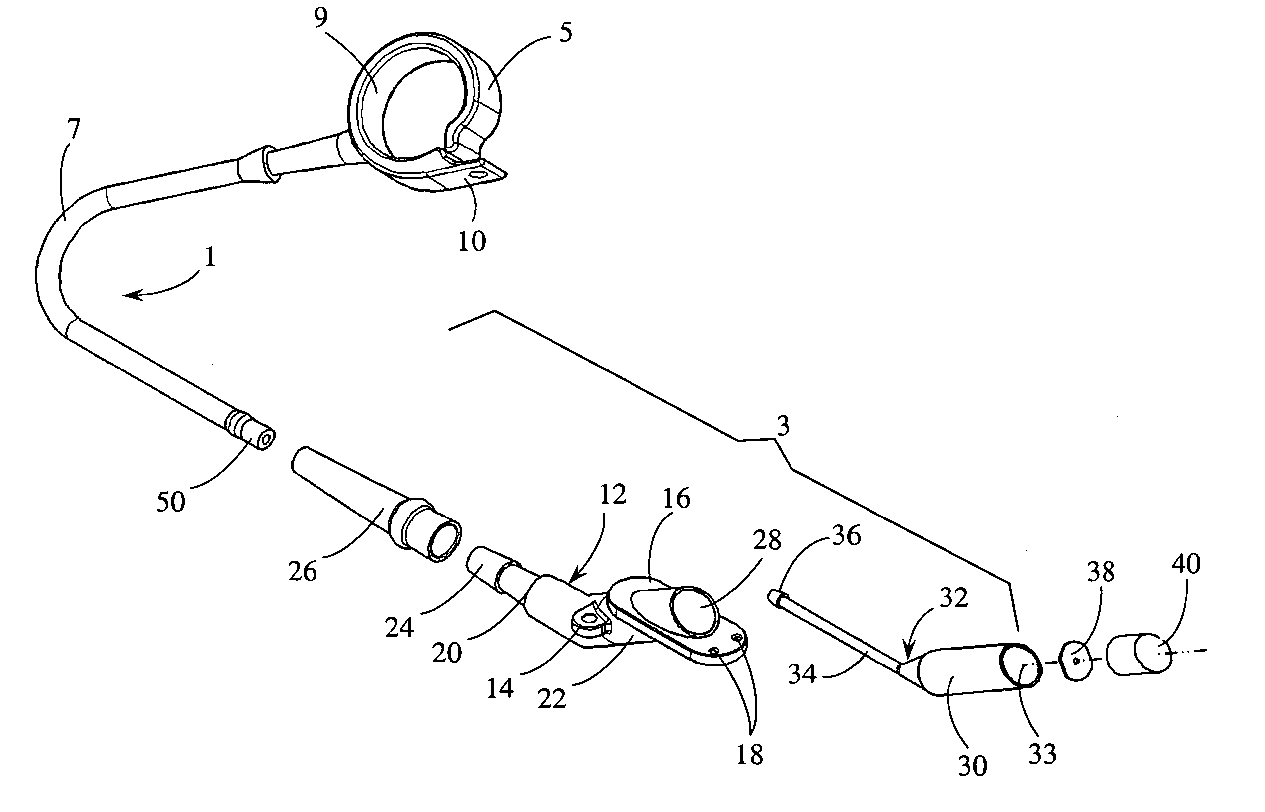
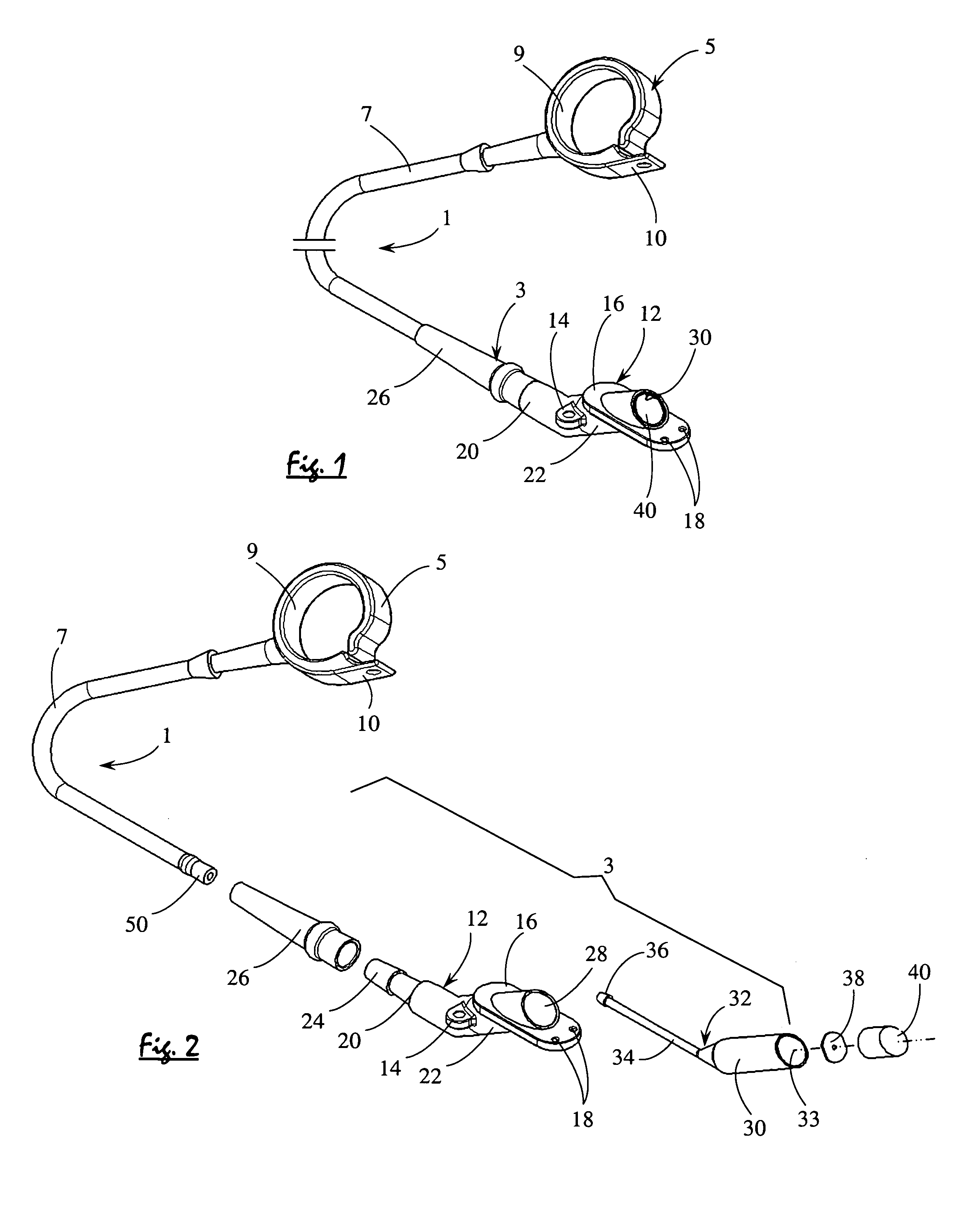
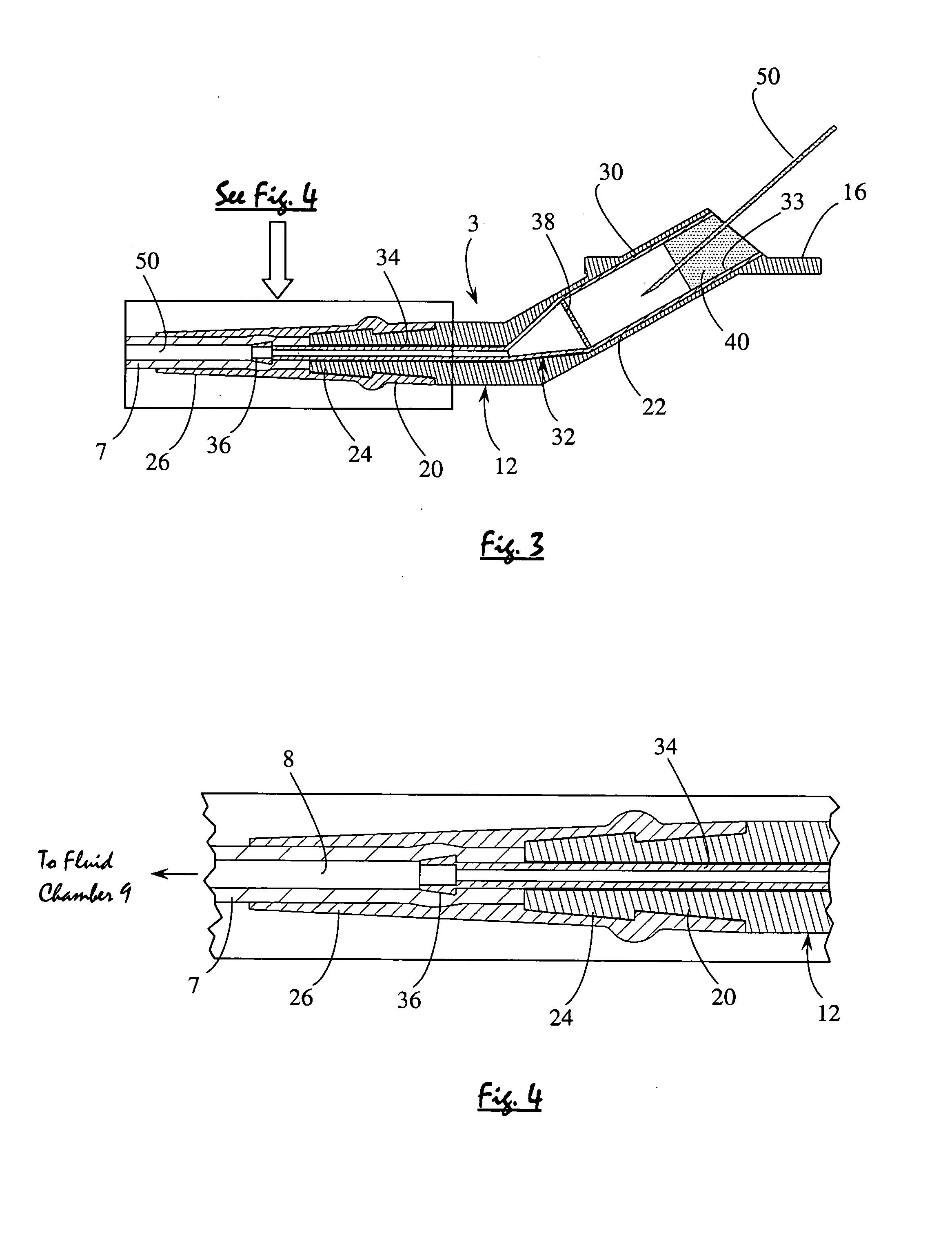
[0009]The improved fluid port includes an outer body that is molded around a rigid inner liner which is preferably manufactured from stainless steel, or the like. The inner liner includes a relatively wide fluid reservoir within which a needle cannula is inserted so that fluid can be added to or removed from the inflatable fluid chamber of the constriction collar. The inner liner also includes a relatively narrow reservoir extension projecting outwardly from the fluid reservoir to be mated to the fluid tubing of the banding system. A needle stop plate and a self-healing gel plug are located within the fluid reservoir of the inner liner to limit the movement of the needle cannula therethrough and to automatically close any puncture wounds created by the cannula.
[0010]The outer body of the fluid port includes a fluid inlet end to surround the fluid reservoir of the inner liner and a fluid outlet end to surround the reservoir extension. The fluid reservoir and the reservoir extension of the inner liner as well as the fluid inlet and outlet ends of the outer body are aligned relative to one another at an angle (e.g., approximately 135 degrees). In this manner, the rigid inner liner will be configured so that clinicians can quickly and easily palpate and locate the fluid reservoir thereof following implantation so as to be able to accurately insert the needle cannula in order to selectively adjust the occlusive pressure generated by the inflatable fluid chamber of the constriction collar.
[0011]The outer body of the fluid port includes attachment wings projecting therefrom to receive surgical sutures for attachment to the patient's tissue (e.g., the facia layer within an area of the abdominal wall characterized by reduced fat and muscle and located adjacent the xiphoid bone at the bottom of the sternum) so as to minimize movement of the fluid port following implantation. The outer body also includes a flat horizontal base extending therearound. During implantation of the fluid port, the flat base is positioned to rest upon the outside of the patient's facia tissue layer (i.e., the upper portion of the linea alba) to which the fluid port is sutured, and the attachment wings are positioned against the opposite inside of the facia tissue layer so that the fluid reservoir of the inner liner will be located in an easily palpable position in the subcutaneous fat and oriented so as to be quickly and easily identified and located by means of palpating the patient's skin below the sternum The ease of locating the fluid port and its proximity to the skin allows a reduction in size such that the port will pass through a small laparoscopic incision.
[0012]A strain relief collar extends between the fluid tubing and a taper formed at the fluid outlet end of the outer body of the fluid port. The strain relief collar reduces fatigue and stress buildup at the union of the fluid port and the fluid tubing so as to reduce the possibility of fracture and improve the reliability of the gastric banding system following implantation.

Problems solved by technology

Several problems persist with most known fluid port devices as a consequence of using a conventional fluid port with a gastric banding system that is surgically implanted within the abdominal cavity of an obese patient.
Such stress and fatigue have resulted in a fracture, a leak of fluid into the patient's abdominal cavity, and an ultimate failure of the banding system.
Another significant problem is the difficulty faced by clinical personnel when trying to detect and access the conventional fluid port through the fatty tissue of the obese patient so as to be able to properly insert a needle cannula therein.
Thus, it has proven difficult for a surgeon to find a firm tissue area to which the fluid port can be sutured so as to minimize movement and provide resistance for cannula insertion.
Should an emergency condition arise when it is necessary to immediately reduce the occlusive pressure being generated by the constriction collar around the patient's stomach, emergency room medical personnel have experienced difficulty in being able to quickly find the precise location and orientation of the fluid port for receipt of the cannula.
Therefore, some emergency room physicians and other clinicians are reluctant to take prompt action because they are not entirely certain where to insert the cannula.
In this case, a very long cannula is often used which may result in the patient's abdominal wall being pierced and his internal organs suffering injury.
In another case, the fluid tubing associated with the fluid port could be accidentally punctured and damaged.
If the needle cannula is inserted at the wrong location, time will be wasted and relief will be delayed as the patient is exposed to successive needle sticks until the correct location of the fluid port is finally identified.
In this same regard, in order to increase the target area for a successful placement and insertion of a needle cannula through the fatty tissue, the size of the fluid port has had to remain large, which excludes the port from laparoscopic implantation and has resulted in a larger incision to reach the abdominal wall causing more tissue trauma and pain, at the time of surgical implantation.

Method used


Image

  • Fluid port for an adjustable gastric banding system
  • Fluid port for an adjustable gastric banding system
  • Fluid port for an adjustable gastric banding system

Examples


Embodiment Construction

[0019]Referring initially to FIGS. 1 and 2 of the drawings, a gastric banding system 1 is shown including the improved fluid port 3 according to a preferred embodiment of this invention. The gastric banding system 1 of FIGS. 1 and 2 has particular application to be laparoscopically-implanted around the upper stomach of an obese patient seeking a procedure to help in weight reduction The fluid port 3 is configured so as to be quickly and easily located following implantation, whereby medical personnel can inject (or remove) a suitable (e.g., saline solution) fluid by which to selectively adjust the occlusive force generated by an inflatable constriction collar 5 of the banding system 1 which is located in surrounding engagement with the stomach of the patient.

[0020]Inasmuch as the inflatable constriction collar 5 and its fluid tubing 7 of banding system 1 are commercially available surgical devices, only a brief description thereof will be provided herein. Constriction collar 5, some...


PUM


Abstract

An improved fluid port for use in an adjustable gastric banding system that can be laparoscopically-implanted around the upper stomach of an obese patient as part of a procedure to help in weight reduction. The improved fluid port is coupled to a conventional constriction collar of the banding system by way of bio-compatible fluid tubing. The fluid port includes a rigid liner having a needle cannula receiving fluid reservoir at one end thereof at which fluid is added to or withdrawn from the constriction collar and a reservoir extension at the opposite end to be mated to the fluid tubing. The fluid reservoir and the reservoir extension are aligned with one another at an angle so as to be oriented following implantation (e.g., below the xiphoid bone where layers of fat and muscle are minimal) to be quickly and easily located by palpating the patient's skin at the bottom of the sternum immediately below the xyphoid process. A stress relief collar surrounds the connection of the reservoir extension of the inner liner to the fluid tubing so as to reduce fatigue and avoid a possible fracture, whereby to enhance the reliability of the fluid port.

Description

BACKGROUND OF THE INVENTION[0001]1. Field of the Invention[0002]This invention relates to an improved fluid port for use in a gastric banding system that is suitable to be laparoscopically-implanted around the upper stomach of an obese patient during a procedure to help in weight reduction. The improved fluid port has a configuration that establishes an easy-to-locate target area, following implantation, for receipt of a needle cannula to permit fluid to be injected into or removed from a constriction collar of the banding system to selectively adjust the occlusive pressure generated thereby.[0003]2. Background Art[0004]Gastric banding systems are known which have been surgically implanted around the stomach of an obese patient to generate an occlusive pressure by which to create an early sensation of being full and thereby reduce food intake as part of a weight reduction program. A gastric banding system is commonly implanted with a fluid port at which fluid can be supplied to or r...

Claims


Application Information

Patent Timeline
Patent Type & Authority Applications(United States)
IPC IPC(8): A61B17/12
CPCA61F5/0056A61F5/003
Inventor QUEBBEMANN, BRIAN B.FOSTER, CLARK B.
Owner QUEBBEMANN BRIAN B
Learn More