
Electro-Rheological Fluid Brake and Actuator Devices and Orthotic Devices Using the Same

Inactive Publication Date: 2008-04-24
NORTHEASTERN UNIV
View PDF15 Cites 134 Cited by
  • Summary
  • Abstract
  • Description
  • Claims
  • Application Information

AI Technical Summary

Benefits of technology

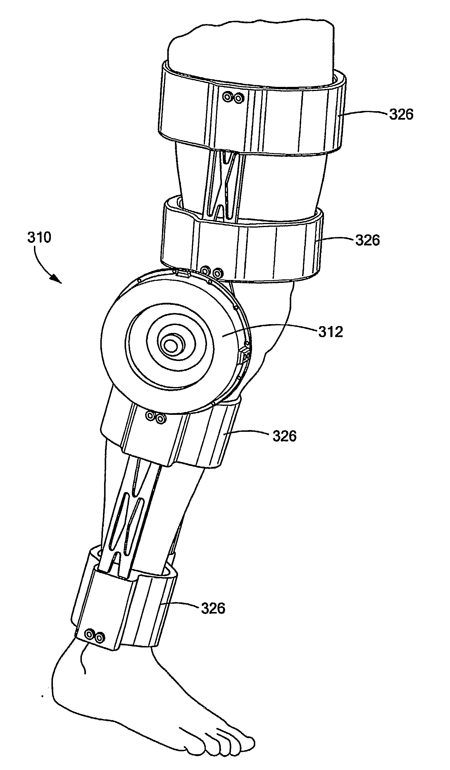
[0008] The present invention also relates to an orthotic device that is portable and controllable by a motive device that can provide variable resistance and / or actuating functionalities, utilizing preferably an ERF brake / damper or actuator as described above. In one embodiment, the orthotic ERF brake / damper device according to the invention is compact and lightweight with strong, highly tunable torque capabilities, fully portable and wearable with onboard sensors, power and control circuitry, and real time capabilities for closed loop computer control for optimizing rehabilitation exercises while in use. In a further embodiment, an orthotic device according to the invention includes an actuator as an active feature. Preferably, this orthosis exhibits all the characteristics of the resistive device as well as the additional abilities to force motion of the knee, perform muscle enhancement and provide force feedback.

Problems solved by technology

Such motors can be difficult to control for certain applications and may be large and heavy.
DC motors are not ideal in many cases for providing resistive control or braking for these and other reasons.
It is disadvantageous in that it generates heat, is subject to wear and reliability problems, and can be harmed by contaminates.
Magnetic brakes are known and used for resistive control, but not for providing an output torque.
They also generate heat and can be hard to control and provide a “jerky” engagement.
The MRF brake similarly is not useful for providing an output torque.
It is also subject to excessive heat generation and can be heavy and large.
Thus, these known types of actuators can either control output torque or modulate input torque, but none of them can perform both functions.
Generally, these devices are limited to retraining the natural gait motion and to muscle enhancement.
These devices tend to be bulky and cumbersome, which hinders their use, and the inclusion of active elements increases the overall size, cost and weight.

Method used


Image

  • Electro-Rheological Fluid Brake and Actuator Devices and Orthotic Devices Using the Same
  • Electro-Rheological Fluid Brake and Actuator Devices and Orthotic Devices Using the Same
  • Electro-Rheological Fluid Brake and Actuator Devices and Orthotic Devices Using the Same

Examples


Embodiment Construction

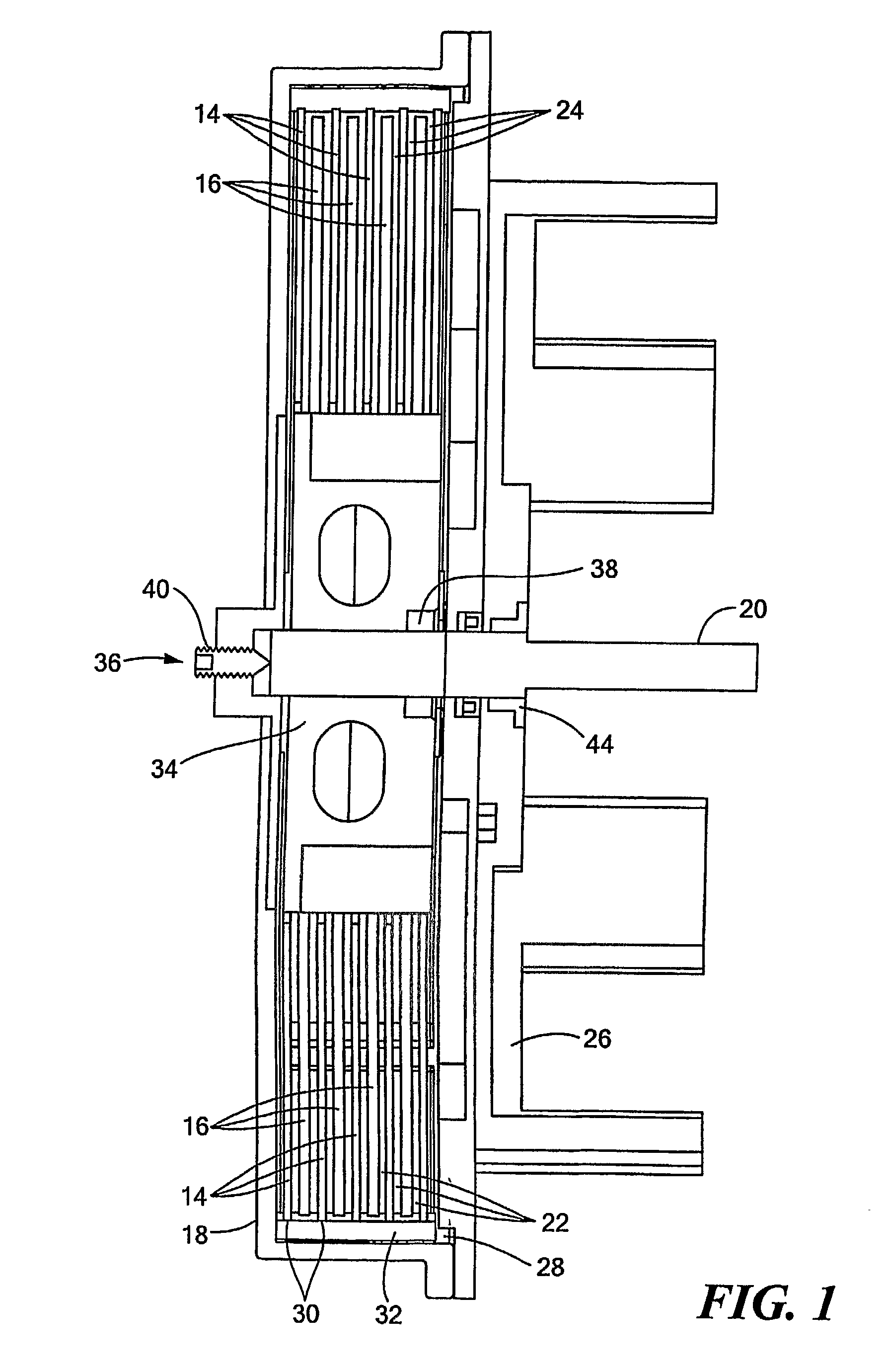
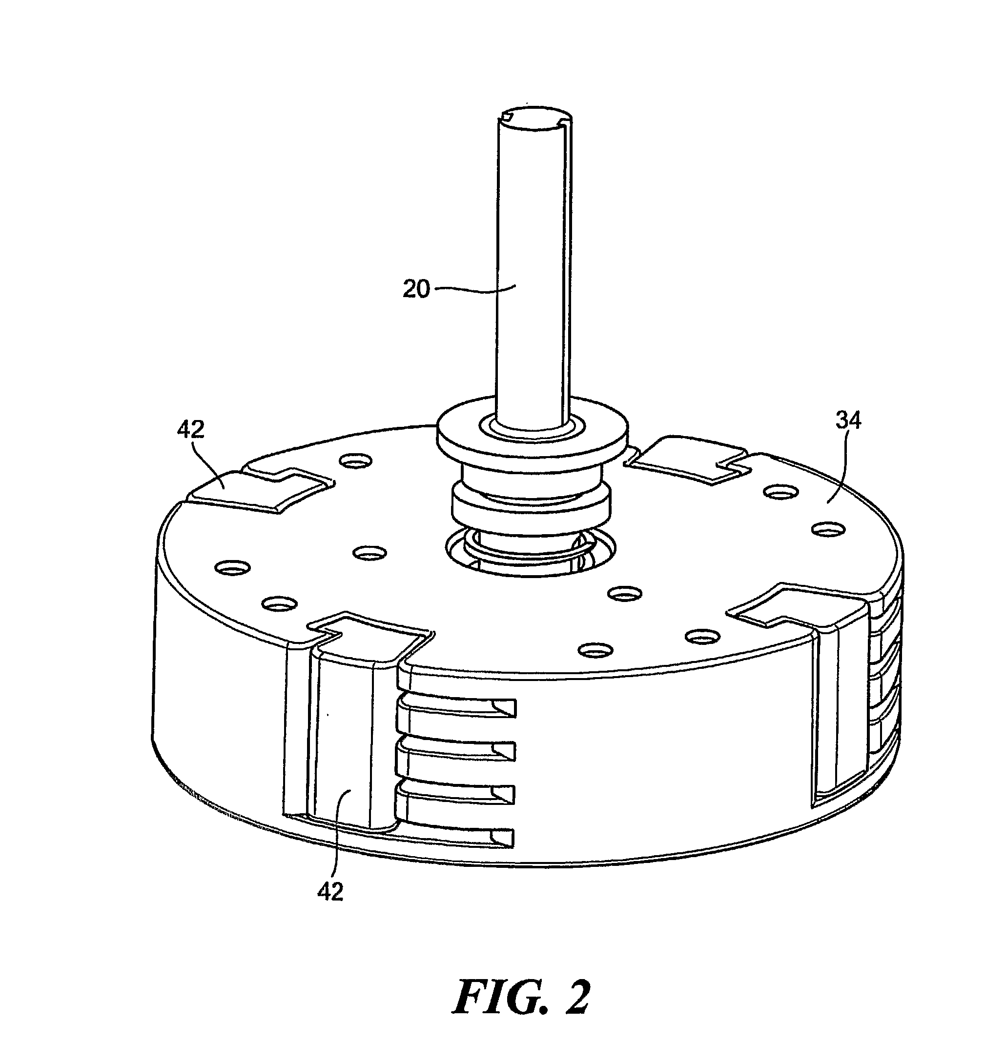
[0047] Electro-rheological fluids experience changes in Theological properties, such as viscosity, in the presence of an electric field. The fluids are made from suspensions of particles on the order of 0.01 to 0.1 μm in size in an insulating base fluid, such as an oil. The volume fraction of the particles is generally between 20% and 60%. The electro-rheological effect, sometimes called the Winslow effect, is thought to arise from the difference in the dielectric constants of the fluid and particles in the electro-rheological fluid (ERF). In the presence of an electric field, the particles, due to an induced dipole moment, form chains along the field lines. The induced structure changes the ERF's viscosity, yield stress, and other properties, allowing the ERF to change consistency from that of a liquid to something that is viscoelastic, such as a gel, at response times on the order of milliseconds. ERFs can apply very high electrically controlled resistive forces while their size (...


PUM


Abstract

Electro-rheological fluid brake or actuator devices provide controllable resistance with or without inclusion of active torque output in either direction of rotation under manual or computer control. The brake and actuator devices are suitable for use in an orthotic device for a joint, such as the knee or elbow.

Description

CROSS REFERENCE TO RELATED APPLICATIONS [0001] This application claims the benefit under 35 U.S.C. § 119(e) of U.S. Provisional Patent Application No. 60 / 626,256, filed on Nov. 9, 2004, and U.S. Provisional Patent Application No. 60 / 626,365, filed Nov. 9, 2004, the disclosures of which are incorporated by reference herein.STATEMENT REGARDING FEDERALLY SPONSORED RESEARCH OR DEVELOPMENT [0002] N / A BACKGROUND OF THE INVENTION [0003] Various types of actuators and brakes are known. For instance, a DC motor can be used as an actuator to control output torque. Such motors can be difficult to control for certain applications and may be large and heavy. Increasing the output torque generally requires increasing the size of the motor. DC motors are not ideal in many cases for providing resistive control or braking for these and other reasons. As another example, a friction brake can be used for resistive control but not for providing an output torque. It is disadvantageous in that it generat...

Claims


Application Information

Patent Timeline
IPC IPC(8): A61F5/01A61F2/74F16F9/53
CPCA61F2/68A61F5/0125F16F9/532A61F2002/6818F16D57/002A61F2002/5004A61F2/70
Inventor WEINBERG, BRIANNIKITCZUK, JASONMAVROIDIS, CONSTANTINOS
Owner NORTHEASTERN UNIV
Learn More